1066540000/00/02.09
47
51
52
53
54
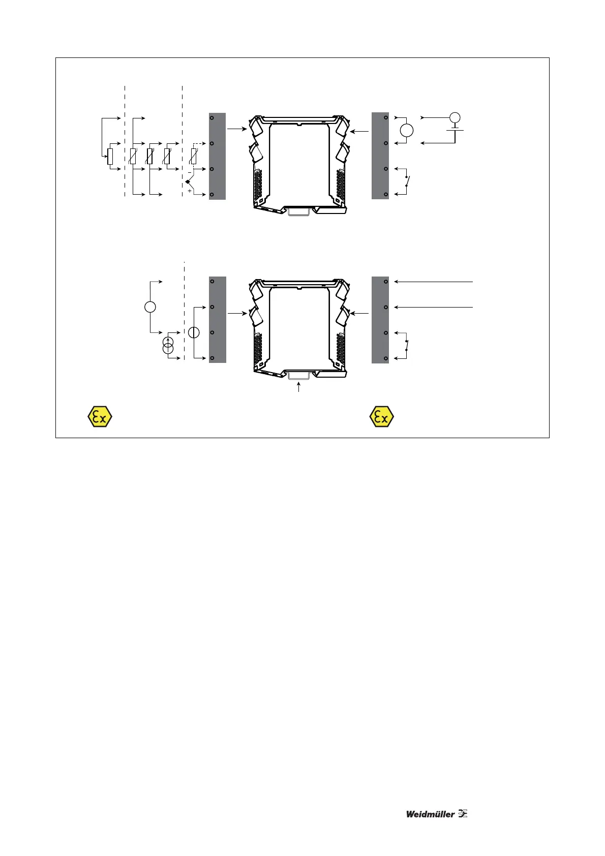
Input signals Output signals
Power connection
Gnd.
Supply +19.2...31.2 VDC
N.C.
Device status
Supply via
power rail
Device status
Zone 0, 1, 2, 20, 21, 22 /
Cl. I/II/III, div. 1 gr. A-G
Zone 2 / FM Cl. 1,
div. 2, gr. A-D or safe area
+
+
14
13
12
11
24
23
22
21
+
-
Tx
Current Voltage
Potenti-
ometer
RTD and lin. R TC
* Order separately:
CJC connector 5910Ex
Connection, wires
+
-
42
41
44
43
14
13
12
11
+
Analogue, 0/4...20 mA and relay
mA
mA
Relay
Relay
N.O.
Channel 1:
Channel 2:
*
Illustration 7-12: Applications
Specifications
RTD, linear resistence and potentiometer input
Input type Min. value Max. value Standard
Pt100 -200 °C +850 °C IEC 60751
Ni100 -60 °C +250 °C DIN 43760
Linear resistence 0 Ω 10 000 Ω –
Potentiometer 10 Ω 10 000 Ω –
Input for RTD types Pt10*, Pt20*, Pt50*, Pt100, Pt200, Pt250, Pt300,
Pt400, Pt500, Pt1000, Ni100, Ni120, Ni1000
Cable resistance per wire (max.), RTD 50 Ω
Sensor current, RTD Nom. 0.2 mA
Effect of sensor cable resistance (3-/4-wire), RTD < 0.002 Ω / Ω
Sensor error detection, RTD Programmable ON / OFF
Short circuit detection, RTD Yes
*No short circuit detection for Pt10, Pt20 and Pt50
*No short circuit detection for Lin.R_0% ≤ app. 18 Ω