Installation and operating instruction
Combustion manager W-FM 100 und W-FM 200
10 Technical documentation
83054802 1/2018-07 La
219-228
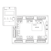
10.1.1 Frequency converter Nord size I … III
1 Interfaces
2 DIP switches
3 Diagnostic LED's
Interface
The interface is used to access the frequency converter via a PC.
The Software required can be found on the Frequency Converter CD.
A connection cable RJ12 to SUB-D9 is required for the connection (Order No. 743
361). A readily available USB interfaces converter USB to RS232 is also required
for the connection to the USB port.
DIP switches
The analogue inputs AIN1 and AIN2 are configured via setting of the DIP switches.
Factory setting (4 … 20 mA):
Switch 1: ON
Switch 2: ON
Diagnostic LED's
LED Signal Description
1 (BUS-S) – System bus status (not used)
2 (BUS-E) – System bus fault (not used)
3 (DS) OFF No mains voltage and no control voltage
Green Operation, FC operating
Flashing green 0.5Hz
(1
Ready for operation
4Hz
(1
Start blocked
Flashing red/green 4Hz
(1
Warning
1 … 25Hz
(1
Intensity overload
Flashing red
Number ≙ flashing codes
Fault, flashing codes see Frequency
converter CD
(1
1Hz ≙ once per second
 Loading...