Installation and operating instruction
Combustion manager W-FM 100 und W-FM 200
3 Product description
83054802 1/2018-07 La
33-228
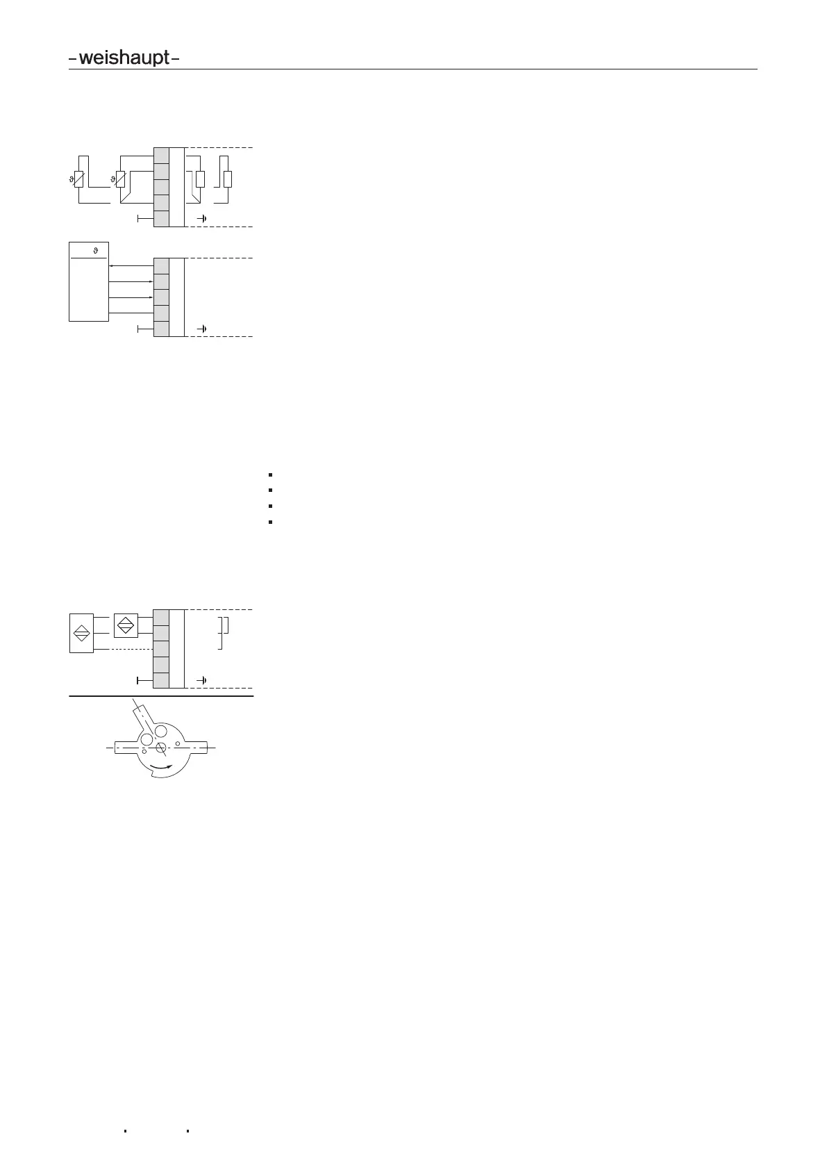
3.3.20 Temperature sensor
FE
2
3
X60
4
5
1
Pt100
Pt/Ni 1000
Pt100Pt/Ni 1000
P /
FE
0
4-20 mA
0-10 V2
3
X61
4
5
1
Power Supply
Sensor
TEMP.TEMP./PRES. INPUT
4...20 mA
GND
IN
0....10 V
If the internal load controller is activated in parameter LC_OptgMode , a temper-
ature sensor has to be connected to input X60 or a temperature or pressure sensor
has to be connected to input X61.
On W-FM 200 with flue gas recirculation(FGR), the FGR temperature sensor is
connected to inputX60:3/4 as standard and is not available for the load controller.
As an alternative, the flue gas temperature sensor on the O2 module (accessory)
can be used as FGR temperature sensor [ch.3.3.23]. The sensor used must be
defined in parameter FGR-sensor, see [ch.6.15.3].
On W-FM 200 with CO control the combustion air sensor is fitted to inputX60:3/4
and is not available for the load controller. Parameter AirTempX60PT1000
(OEM level) must be set to activated .
The internal temperature monitor function is only possible with temperature sensor
on input X60. If there is no external safety temperature limiter available in the safety
circuit, two temperature sensors (Pt100/Pt1000 or Pt100/Ni1000) must be con-
nected for the internal temperature monitor function.
With different cable resistances in the three-wire circuit (Pt100) line compensation
is required.
Depending on the circuitry, the inputs must be configured via the following para-
meters:
Sensor selection [ch.6.12.3]
Ext Inp X61 U/I [ch.6.12.4]
Measuring range [ch.6.12.5]
Additional sensor for boiler start function [ch.6.12.14].
The voltage supply (20VDC) on terminalX61:1 can not be changed.
3.3.21 Speed measurement
FE
0
RESERVE
Pulse-In
Usensor
2
3
X70
5
4
1
2 wire
3 wire
BN
BU
BN
BK
BU
For operation with frequency converter (W-FM 200 only) the proximity switch for
speed measurement is connected to input X70.
Via the transmitter disc, the proximity switch detects 3 impulses per rotation. The
number of impulses must be defined in parameter Num Puls per R, see
[ch.6.14.2]. The direction of rotation is detected by the asymmetrical transmitter
disc (60°, 120°, 180°).
 Loading...