Installation and operating instruction
Gas burner WG20…/1-C Z-LN
7 Commissioning
83054602 1/2020-01 La
43-96
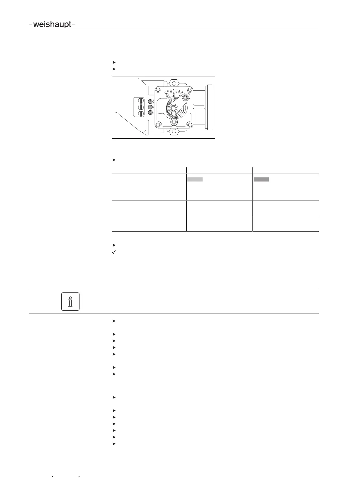
3. Adjust ignition load
Check combustion values in ignition load.
Set O2 content of 4 … 5 % via gas butterfly valve screw1.
4. Adjust full load
Select variation1 or 2 depending on rating selected from setting diagram:
Variation 1 Variation 2
Setting diagram
Actuator
Diffuser
less than 80°
0 mm
greater than 80°
greater than 0mm
Set combustion via: Multifunction assembly
setting pressure
Diffuser
Set capacity via: Air damper setting ST2 Multifunction assembly
setting pressure
Heat demand required for full load (contact T6/T8 closed).
Plug in 4 pole connection plug.
Burner drives to full load.
When adjusting, the ratings data given by the boiler manufacturer and the capacity
graph of the burner should be observed [ch.3.4.6].
Variation 1
Exit full load, if the air damper setting has to be adjusted. Any adjustment to the air
damper setting for full load must be made in partial load.
Check CO content of combustion and if necessary adjust combustion via the
multifunction assembly setting pressure.
Calculate gas throughput (operating volume VB) required [ch.7.6].
Optimise air damper settingST2 until gas throughput (VB) is achieved.
Check combustion values
Determine combustion limit and set excess air via multifunction assembly setting
pressure [ch.7.5].
Determine gas throughput once more and adjust if necessary.
Re-set excess air.
Variation 2
Check CO content of combustion and if necessary adjust combustion values via
diffuser.
Calculate gas throughput (operating volume VB) required [ch.7.6].
Optimise setting pressure until gas throughput (VB) is achieved.
Check combustion values
Determine combustion limit and set excess air via diffuser [ch.7.5].
Determine gas throughput once more and adjust if necessary.
Re-set excess air.

 Loading...