Installation and operating instruction
Gas burner WG20…/1-C Z-LN
7 Commissioning
83054602 1/2020-01 La
44-96
5. Adjust partial load
The following steps must only be carried out for two stage operation. For
single stage operation continue with step 7.
Exit partial load, if the air damper setting has to be adjusted. Any adjustment to the
air damper setting for partial load must be made in full load.
Define partial load, whilst:
observing data provided by boiler manufacturer,
observing the burner capacity graph [ch.3.4.6].
Set partial load via limit switch ST1.
Unplug 4 pole connection plug.
Burner drives to partial load.
Check combustion values
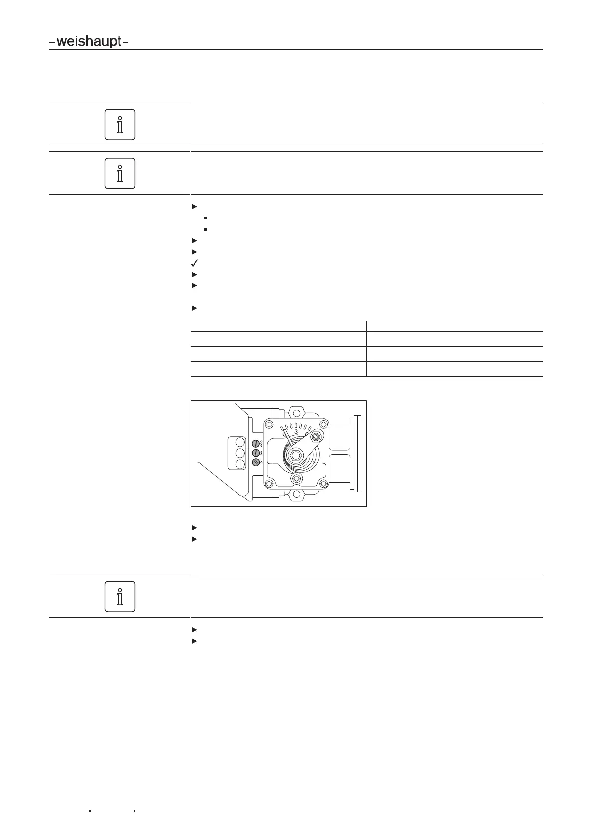
Determine combustion limit and if necessary re-set excess air via gas butterfly
screws.
Observe operational range of gas butterfly screws.
screw Operational range
3 50° … 80°
2 20° … 50°
1 0° … 20°
Factory setting: 3 rotations OPEN.
Determine gas throughput and if necessary adjust.
Re-set excess air.
6. Check full load
Adjustments to the gas setting screws in partial load can lead to combustion value
changes in full load.
Drive to full load.
Check combustion values and if necessary adjust via gas setting screws whilst
observing the operational range of the gas butterfly screws.

 Loading...