13
WT200MP Welding Machine
www.weldtech.net.nz
Gas Metal ARC Welding (GMAW).
Thisprocess,alsoknownasMIGwelding,CO2weld-
ing,MicroWireWelding,shortarcwelding,diptrans-
fer welding, wire welding etc., is an electric arc weld-
ing process which fuses together the parts to be
welded by heating them with an arc between a solid
continuous, consumable electrode and the work.
Shielding is obtained from an externally supplied
welding grade shielding gas. The process is normally
applied semi automatically; however the process
may be operated automatically and can be machine
operated. The process can be used to weld thin and
fairly thick steels, and some non-ferrous metals in all
positions.
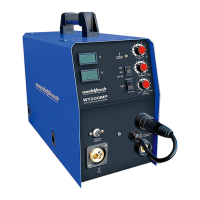
GMAW Process
(Fig 1-1)
ShieldingGas
MoltenWeldMetal
Nozzle
Electrode Arc
BaseMetal
SolidiedWeldMetal
Flux Cored Arc Welding (FCAW)
This is an electric arc welding process which fuses to-
gether the parts to be welded by heating them with
an arc between a continuous ux lled electrode
wireandthework.Shieldingisobtainedthroughde-
composition of the ux within the tubular wire. Ad-
ditional shielding may or may not be obtained from
an externally supplied gas or gas mixture. The pro-
cess is normally applied semi automatically; however
the process may be applied automatically or by ma-
chine.
It is commonly used to weld large diameter elec-
trodes in the at and horizontal position and small
electrode diameters in all positions. The process is
used to a lesser degree for welding stainless steel
and for overlay work.
FCAW Process
(Fig 1-2)
Nozzle
(Optional)
FluxCored
Electrode
Arc
Base
Metal
Solidied
WeldMetal
Slag
Molten
Slag
MoltenMetal
ShieldingGas
(Optional)
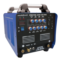
Push
Vertical Drag Pull
Position of MIG Torch
(Fig 1-3)
TheangleofMIGtorchtotheweldhasaneecton
the width of the weld.
The welding gun should be held at an angle to the
weldjoint.(SeeSecondaryAdjustmentVariablesbe-
low).
Holdthegunsothattheweldingseamisviewedat
all times. Always wear the welding helmet with prop-
er lter lenses and use the proper safety equipment.
CAUTION!
Do not pull the welding gun back when the arc is
established. This will create excessive wire exten-
sion (stick-out) and make a very poor weld.
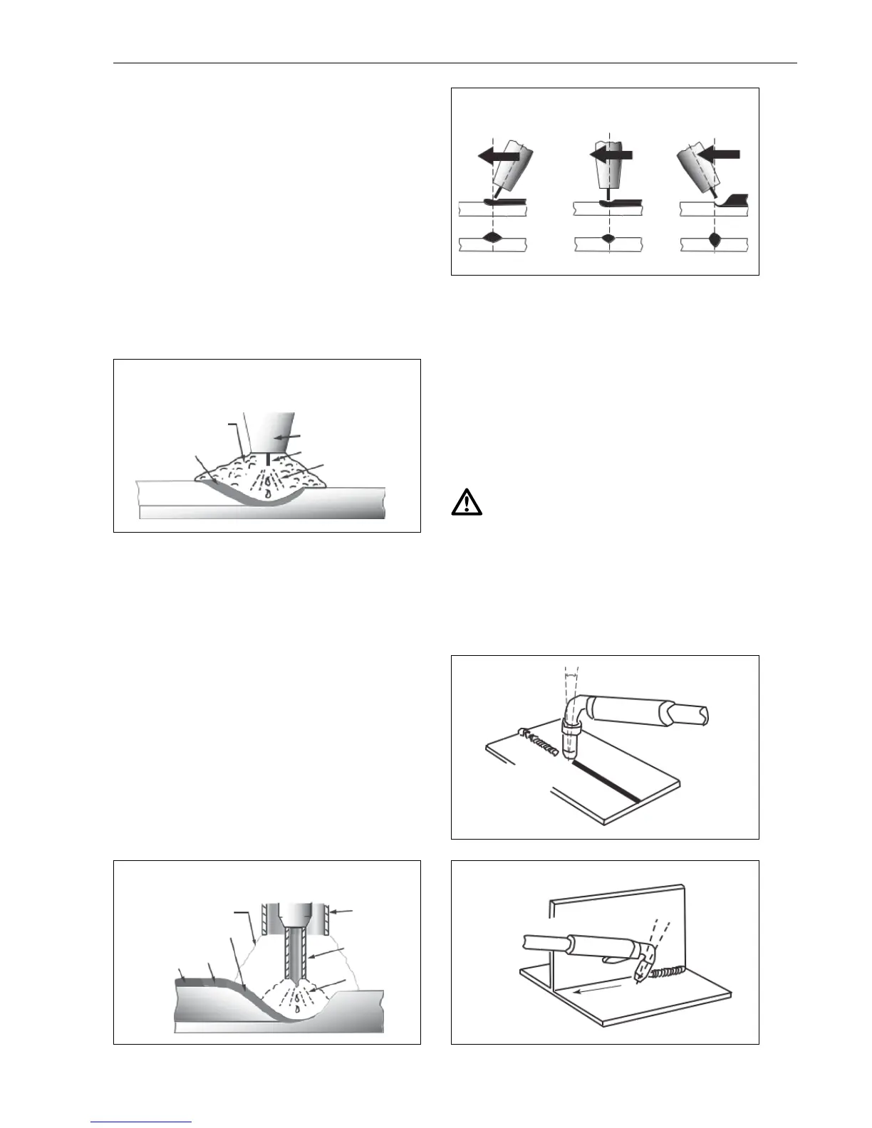
The electrode wire is not energized until the gun
trigger switch is depressed. The wire may therefore
be placed on the seam or joint prior to lowering the
helmet.
(Fig 1-4)
5
o
to15
o
LongitudinalAngle
Direction of Travel
90
o
Transverse
Angle
(Fig 1-5)
5
o
to15
o
LongitudinalAngle
30
o
to 60
o
Transverse
Angle
Direction
of Travel
 Loading...