14
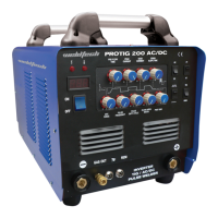
Vertical Fillet Welds (Fig 1-6)
10
o
LongitudinalAngle
Direction of Travel
10
o
to 20
o
LongitudinalAngle
30
o
to 60
o
Transverse
Angle
30
o
to 60
o
Transverse
Angle
Direction of Travel
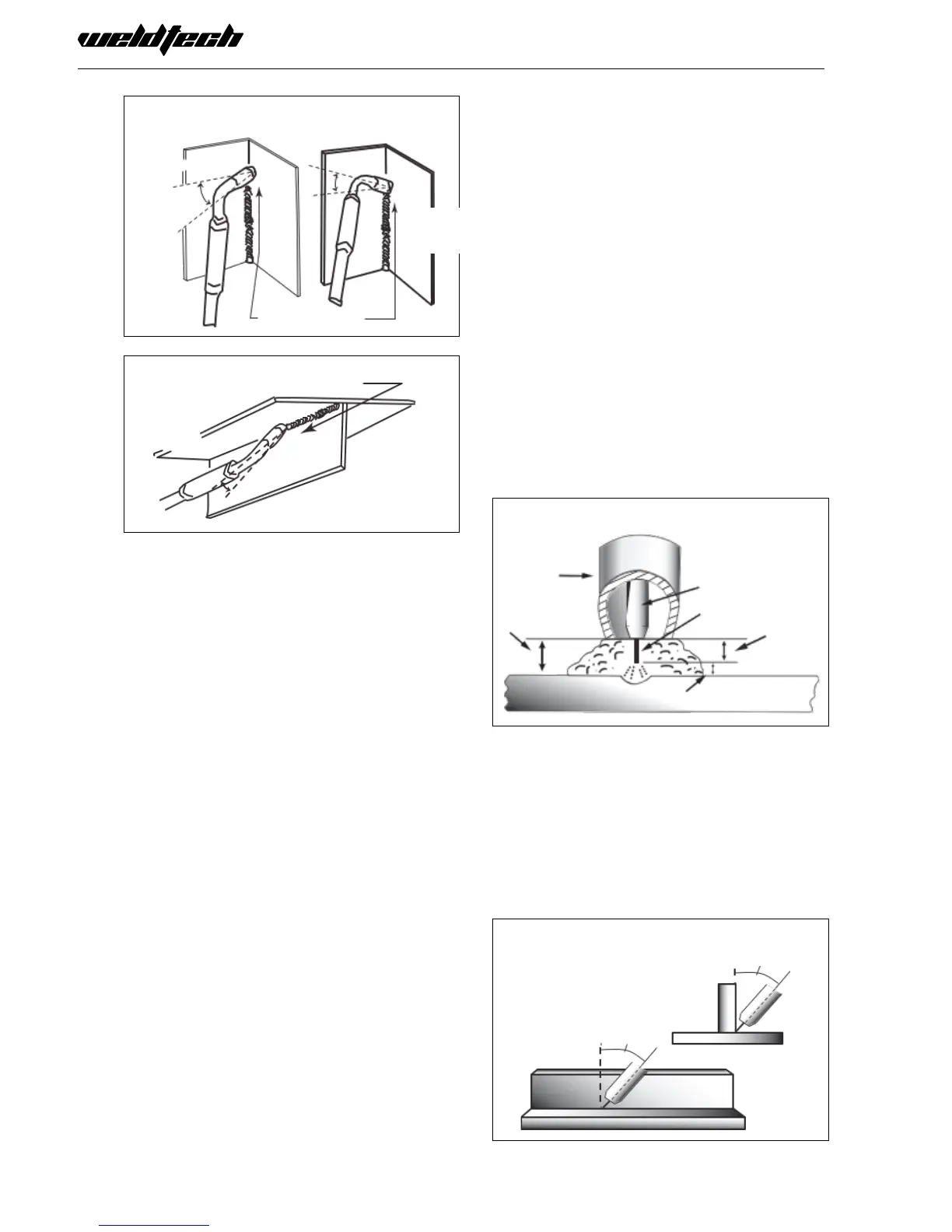
(Fig 1-7)
5
o
to15
o
Longitudinal
Angle
30
o
to 60
o
Transverse
Angle
Distance from the MIG Torch Nozzle
to the Work Piece
TheelectrodewirestickoutfromtheMIGTorchnoz-
zle should be between 10mm to 20mm. This dis-
tance may vary depending on the type of joint that
is being welded.
Travel Speed
The speed at which the molten pool travels inu-
ences the width of the weld and penetration of the
welding run.
MIG Welding (GMAW) Variables
Mostoftheweldingdonebyallprocessesisoncar-
bon steel. The items below describe the welding vari-
ablesinshort-arcweldingof24gauge(0.024”,0.6mm)
to¼”(6.4mm)mildsheetorplate.Theappliedtech-
niquesandendresultsintheGMAWprocessarecon-
trolled by these variables.
Preselected Variables
Preselected variables depend upon the type of ma-
terial being welded, the thickness of the material, the
welding position, the deposition rate and the me-
chanical properties.
These variables are:
• Typeofelectrodewire
• Sizeofelectrodewire
• Typeofgas
• Gasowrate
Primary Adjustable Variables
These control the process after preselected variables
have been found. They control the penetration, bead
width, bead height, arc stability, deposition rate
and weld soundness.
Theyare: • ArcVoltage
• Weldingcurrent(wirefeedspeed)
• Travelspeed
Secondary Adjustable Variables
These variables cause changes in primary adjustable
variables which in turn cause the desired change in
the bead formation. They are:
1. Stick-Out (distancebetweentheendofthecon-
tact tube (tip) and the end of the electrode wire).
Maintainatabout10mmstick-out
2. Wire Feed Speed. Increase in wire feed speed
increases weld current. Decrease in wire feed speed
decreases weld current.
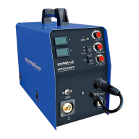
Electrode Stick-Out
(Fig 1-8)
GasNozzle
Tip to
Work Distance
ContactTip(Tube)
Electrode Wire
Actual
Stick-Out
3. Nozzle Angle. This refers to the position of the
welding gun in relation to the joint. The transverse
angle is usually one half the included angle between
plates forming the joint. The longitudinal angle is the
angle between the centre line of the welding gun
and a line perpendicular to the axis of the weld. The
longitudinal angle is generally called the Nozzle
Angle and can be either trailing (pulling) or lead-
Transverse & Longitudinal
Nozzle Axes (Fig 1-9)
LongitudinalAngle
Transverse Angle
Axis of Weld
 Loading...