15
WT200MP Welding Machine
www.weldtech.net.nz
ing (pushing).Whether the operatoris left handed
or right handed has to be considered to realize the
eects of each angle in relation to the direction of
travel.
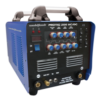
Nozzle Angle, Right Handed Operator
(Fig 1-10)
Direction of Travel
Leadingor“Pushing”
Angle(ForwardPointing)
Trailingor“Pulling”
Angle(BackwardPointing)
90
o
Establishing the Arc and Making Weld Beads
Before attempting to weld on a nished piece of
work, it is recommended that practice welds be
made on a sample metal of the same material as that
of the nished piece.
The easiest welding procedure for the beginner to
experimentwithMIGweldingistheatposition.The
equipment is capable of at, vertical and overhead
positions.
ForpracticingMIGwelding,securesomepiecesof16
or18gauge(1.5mmor2.0mm)mildsteelplate(150
x150mm).Use(0.8mm)uxcoredgaslesswireora
solid wire with shielding gas.
Setting of the Power Source
Power source and Current (WireSpeed) setting re-
quires some practice by the operator, as the welding
plant has two control settings that have to balance.
ThesearetheCurrent(WireSpeed)controlandthe
weldingVoltageControl.
The welding current is determined by the Current
(WireSpeed)control,the current willincrease with
increasedCurrent(WireSpeed),resultinginashorter
arc.LessCurrent(WireSpeed)willreducethecurrent
and lengthen the arc. Increasing the welding voltage
hardly alters the current level, but lengthens the arc.
Bydecreasingthevoltage,ashorterarcisobtained
with a little change in current level.
When changing to a dierent electrode wire dia
eter, dierent control settings are required. A thinner
electrodewireneedsmoreCurrent(WireSpeed)to
achieve the same current level.
A satisfactory weld cannot be obtained if the Current
(WireSpeed)andVoltagesettingsarenotadjustedto
suit the electrode wire diameter and the dimensions
of the work piece.
IftheCurrent(WireSpeed)istoohighfortheweld-
ingvoltage,“stubbing”willoccurasthewiredipsinto
the molten pool and does not melt. Welding in these
conditions normally produces a poor weld due to
lack of fusion. If, however, the welding voltage is too
high, large drops will form on the end of the wire,
causing spatter. The correct setting of voltage and
Current (Wire Speed) can be seen in the shape of
the weld deposit and heard by a smooth regular arc
sound.
Electrode Wire Size Selection
The choice of Electrode wire size and shielding gas
used depends on the following:
• Thicknessofthemetaltobewelded
• Typeofjoint
• Capacityofthewirefeedunitandpowersource
• Theamountofpenetrationrequired
• Thedepositionraterequired
• Thebeadproledesired
• Thepositionofwelding
• Costofthewire
 Loading...