~
fig.36
Twine Retainer Tension
Adjust twine tension spring to distance Q (fig.
32).Themeasuring gauge along side the spring
gi,ves the correct measure. Adjust discrepan-
eies with holt 12.
Distance R is set as fellows end shown in fig.33:
glocken lock nut 1 by tour full turns. Slacken
holt 2 until leGt spring 3 is unloaded. Run down
holt 2, first till it contacts leGt spring 3, then by
exactly 3'/2 turns. This gives spring 3 a pre-
loading of 5 mm. Finally fighten lock nut 1
again.
Adjusting the Twine Flicker
Trip knotters (see fig. 9), turn flywheel in
direction of arrow until flicker 4 (fig. 34) stops
in forward position. Distance S must now be
1-2 mm. If not, glocken lock nuts 5 end turn set
screw 6 as required end secure again.
Twine Stop Spring
Spring 7 (fig. 35) must rest under tension against
nase 8 of twine guide plate. If necessary, bend
spring 7 as required.
Twine Guide fiale
After replacing twine guide plate 9 (fig. 36)
check
DistanceT,clearance betweennase 8 end
knotter heck 10 should be 1.5-2.5mm. If not,
fit shims to adjust twine guide plate 9.
Twine Tensioner
Tighten both wing nuts of twine tensioner 11
end 12 until spring length is 26 mm Distance U.
fig. 37
j
~~
~
~
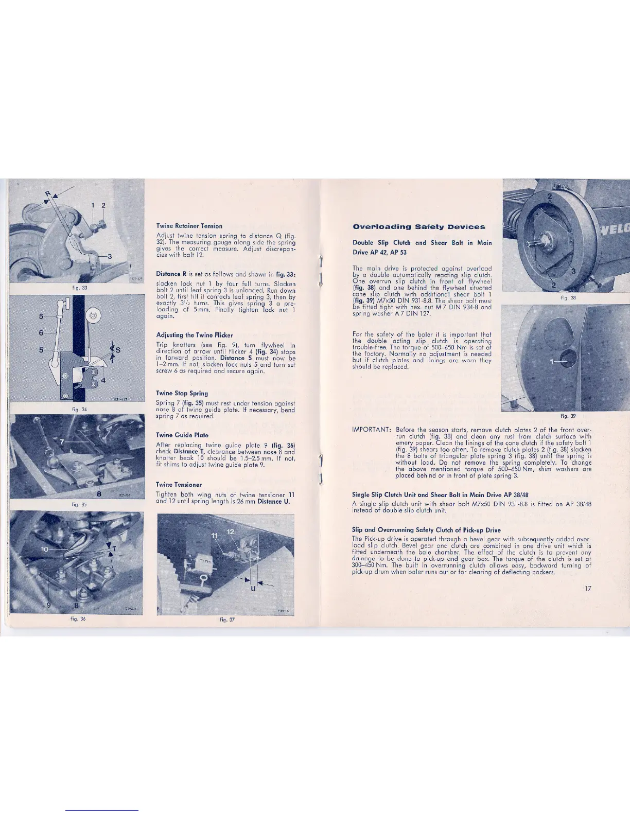
Overloading Safety Devices
Double Slip Clutch and ShearBolt in Main
Drive AP42,AP 53
The mein drive
is protected against overload
by d double automatically reacting slip clutch.
. One overrun slip clutch in front of flywheel
(fig. 38) end one behind ihe flywheel situated
cone slip clutch with additional shear holt 1
(fig. 39) M7x50 DIN 931-8.8. The shear holt musr
.be fitted light with hex. nut M 7 DIN 934-8 end
spring washer A 7 DIN 127.
For the safety of the baler it is important thaI
the double acting slip eluIeh is operating
trouble-free. The torque of 500-650 Nm is se,tat
the factory. Normally no adjustment is needed
hut if clutch plates end linings are warn they
should be replaced.
IMPORTANT:
fig. 38
fig..39
Before the sepsen starts, remove clutch plates 2 of the front. over-
run clutch (fig. 38) end clean any fUgt from clutch surface with
emery paper. Clean the linings of the cone eluIeh if the safety holt 1
(fig. 39) shears tao offen. T0 remove clutch plates 2 (fig. 38) glocken
the 8 halts of triangular pfote spring 3 (fig. 38) until the spring is
without load. Do not remove the spring completely. To chonge
the above mentioned torque of 500,...650Nm, shim washers are
placed behind or in front of plate spring 3.
Single Slip Clutch Unit and Shear Bolt in Main Drive AP 38/48
A single slip alutch unit with shear holt M7x50 DIN 931-8.8is fitted on AP 38/48
instead of double slip clutch unit.
Slip and Overrunning Safety Clutch of Pick-up Drive
The Pick-up drive is operated through abevel geer with subsequently added over-
load slip oIutch. Bevel geer end eluIeh are combined in one drive unit which is
fitted underneath the ba,le chamber. The effect of the clutch is to prevent any
damage to be düne to pick-up end geer box. The torque of the eluIeh is set at
300-450 Nm. The built in overrunning cluleh pIlaws easy, backwardturning of
pick-up drum when baler runs out or für clearing of deflecting packers.
17
 Loading...