1
f,
l'
I
AP 48 D / AP 53 D - Wire Tying
Inserting the Wire
Use only top qua:lity (trade-mark) wire{ note techniwl detai,ls on palge 2, when
ordering. WirB coils shou,ld be neatly end evenly wound. Before fitti,ng coils{
immerse them in eil to compilete saturation. Switch off prof weit until oll moving
parts have come to a complete stop. The wirB box takes two cous as shown
in fig. 44{ !wo spare coih can be placed in the com-
partment behind the packer box. Fit coils wh,ile stil<!
closed by straps{ turns running clock-wise. Do not
tangle the winding turns when cutting the straps.
PuMinner wirB ends out through holes in box. Avoid
kings end loops{ or mistying may result. Fix rree
euter wirB end to box edge.
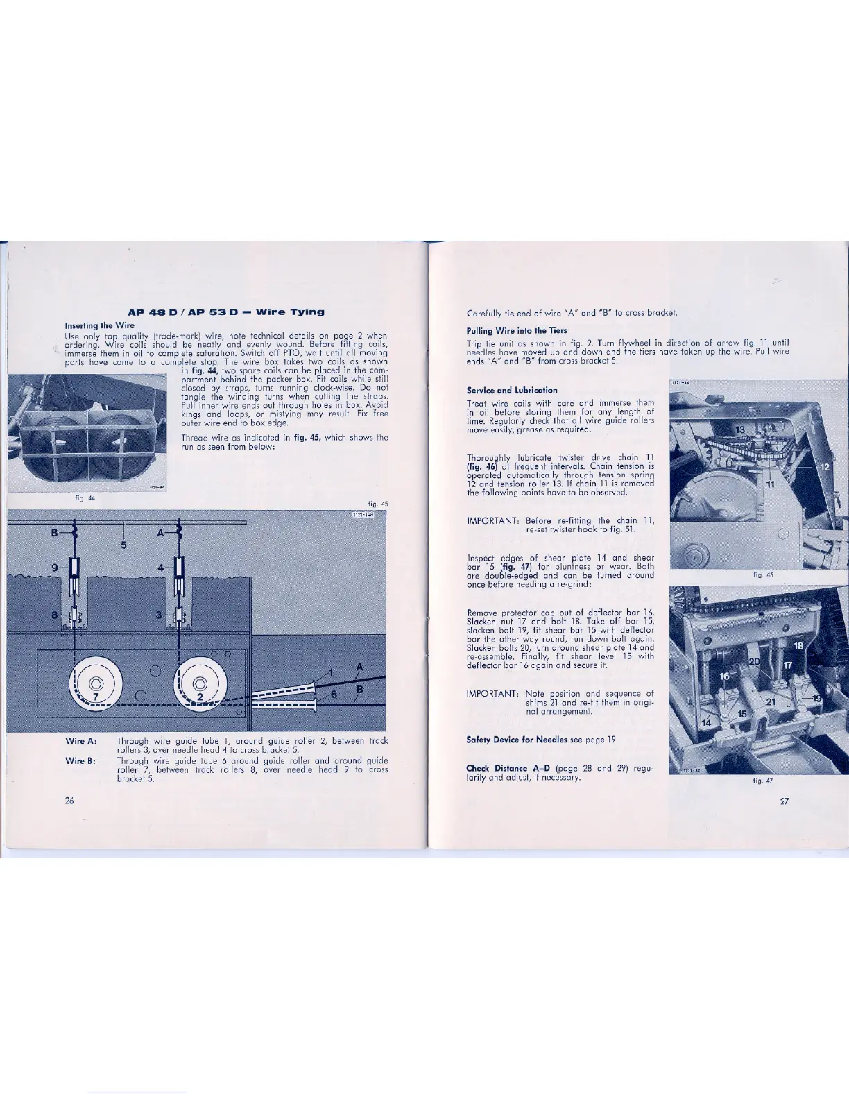
Thread wirB as indicated in fig. 45{ which shows the
run as seen from below:
/-"
Carefully tie end of wirB "A" end "B" to cross bracket.
Pulling Wire info the Tiers
Trip tie unit as shown in fig. 9. Turn flywheE)1 in direction of arrow fig. 11until
needles have moved up end down end the tiers have laken up the wirB. Pull wirB
ends "A" end "B" tram cross bracket 5.
Service and Lubrication
Treat wirB coils with care end immerse them
in eil before storing them tor any length of
time. Regu.larly check thai oll wirB guide rollers
move easi.ly{ grease as required.
Thoroughly lubri,cate twister drive chain 11
(fig. 46) at frequent intervals. Chain tension is
operated automatically through tension spring
12 end tension roller 13. If chain 11 is removed
the following points have to be observed.
IMPORTANT: Before re-fi.tting the chain 11{
re-set twister hock to fig. 51.
Inspect edges of shear plate 14 end shear
bar 15 (fig. 47) tor bluntness or wear. Both
are double-edged end can be turned around
once before needing are-grind: '
Remove protE!cta,r cop out of deflector bar 16.
Slacken nut 17and bolt 18. Take off bar 15{
slacken ball 19{ fit shear bar 15 with deflector
bar the ether war round{ run down ball aga in.
Slacken balls 20{ turn around shear pIlote 14 end
re-assemble. Fina.I,ly{ fit shear level 15 with
deflector bar 16 again end secure i1'.
IMPORTANT: Note positionand sequence of
shims 21 end re-fit them in origi-
nal arrangement.
Safety Device for Needles see page 19
Wire B:
Through wirB guide tube 1{ around guide roller 2{ between track
rollers 3{ over needle head 4 to cross bracket 5.
Through wirB guide tube 6 around guide roller end around guide
roller 7{ between t~ack rollers 8{ over needle head 9 to cross
bracket 5.
Check Distance A-D (page 28 end 29) regu-
larily end adjust{if necessary.
26
fig.47
27