f
~
14
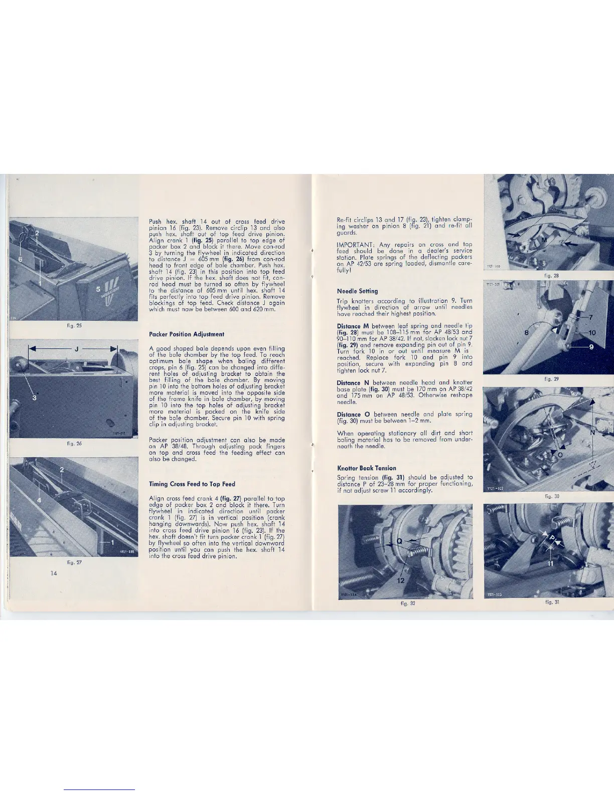
Pushhex. shaft 14 out of cross lead drive
pinion 16 (fig. 23). Removecirclip 13 and also
push hex. shaft out of top feed drive pinion.
Align crank 1 (fig. 25) para-liel to top edge of
packer box 2 and block it there. Move con-rod
3 by turning the flywhee-Iin indicated di,rection
to distance J = 605 mm (fig. 26) from con-rod
head to front edge of bole chamber. Push hex.
shaft 14 (fig. 23) in this position info top feed
drive pinion. If the hex. shaft does not fit, con-
rod head must be turned so offen by lIywheel
to the distance of 605mm until hex. shaft 14
fils perfectly info top lead drive pinion. Remove
blockings of top feed. Check distance J again
which must now be between 600 end 620 mm.
Packer Position Adjustment
A good shaped bole depends upon even filling
of the bole chamber by the top feed. To reach
optimum bole shops when baling different
crops, pin 6 (fig. 25) can be changed info diffe-
rent holes of adjusting bracket to obtain the
best fi,lIing of the bole chamber. By moving
pin 10 info the bollom holes of adjusting bracket
more material is moved info the opposite side
of the frame knife in bole chamber, by moving
pin 10 info the ,top holes of adjusting bracket
more material is packed on the knife side
of the bole chamber. Secure pin 10 with spring
clip in adjusting bracket.
Packer position adjustment can a.lso be made
on AP 38/48. Through adjusting pack fingers
on top end cross lead the feeding effect can
also be changed.
Timing Cross Feed to Top Feed
Align cross lead crank 4 (fig. 27) parallel to top
edge of packer box 2 end block it there. Turn
flywheel in indicated direction until packer
crank 1 (hg. 27) is in vertiwl position (crank
hanging downwards). Now push hex. shaft 14
info cross feed drive pinion 16 (fig. 23). If the
hex. shaft doesn't fit turn packer crank 1 (fig.27)
by flywheel so offen info the vertical downward
position until you canpush the hex. shaft 14
info the cross feed drive pinion.
:t
Re-fit circlips 13 end 17 (fig. 23), tighten clamp-
ing washer on pinion 8 (fig. 21) end re-fit oll
guards.
IMPORTANT: Any repairs on cross end top
feed shou-Id be clone in a dealer's service
station. Plots springs of the deflecling packers
on AP 42/53 are spring loaded, dismant,le care-
fu'lly!
Needle Setting
Trip knollers according to 'illustration 9. Turn
flywheel in direction of arrow until needles
have reached their highest posi,tion.
Distance M betweenleaf spJing end needle tip
(fig.28) must be 108-115mmtor AP 48/53end
90-110mmtor AP38/42.Ifnot,slackenlocknut7
(fig.29) end remove expanding pin out of pin 9.
Turn lork 10 in or out until measure M is
reached. Rep,lace fork 10 end pin 9 info
position, secure with expanding pin 8 end
fighten 'lock nut 7.
Distance N between needle head end knoller
base plots (fig.30)mustbe 170mmon AP38/42
end 175mm on AP 48/53. Otherwise reshape
needle.
Distance 0 between needle end plots spring
(fig. 30) must be between 1-2 mm.
~,
When operating slationary oll dirt end short
baling materia,1has to be removed from under-
neath the needle.
Knotter Beak Tension
Spring tension (fig. 31) should be adjusted to
di,stance P of 23-28 mm tor proper functioning,
if not adjust screw 11accordingly.
fig.32
fig. 28
fig. 29
fig. 30
fig.31