ASSEMBLY & ADJUSTMENTS
WARNING! Unplug the machine from the power source before assembly and making adjustments. Failure
to comply may cause serious injury. Assembly requires at least two people to safely move around the band saw.
ASSEMBLING THE TABLE
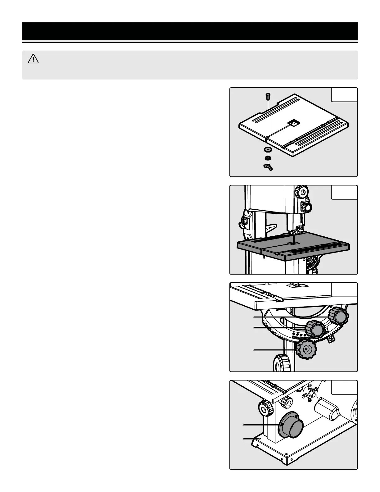
1. Remove the M6x24 hex bolt, spring washer, flat washer and wing
nut from the work table assembly (Fig. 2).
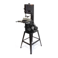
2. Slide the saw table onto the band saw, making sure that the blade
stays within the slot in the table (Fig. 3).
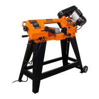
3. Pull the angle adjustment knob (Fig. 4 - 1) on the back of the band
saw and align the teeth on the table bracket into the teeth on the
angle adjustment knob. Release the knob.
3. Assemble the flat washers and table lock knobs (Fig. 4 - 2) into the
table bracket. Turn the table lock knobs to tighten the table assembly
to the saw’s frame.
4. Reattach the hex bolt, spring washer, flat washer and wing nut
onto the front of the table (Fig. 2).
TILTING THE TABLE
1. Loosen the two table lock knobs located on the back of the band
saw (Fig. 4 - 1).
2. Adjust the table to the desired angle using the angle adjustment
knob (Fig. 4 - 2) and the angle indicator. The table can be tilted 45
degrees to the right.
3. Use the angle indicator to confirm the desired angle and tighten
the table lock knobs.
NOTE: A table perpendicular to the blade corresponds to a scale in-
dication of 0°.
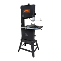
MOUNTING THE BAND SAW
The band saw should be firmly attached to a reliable work surface.
This will prevent the band saw from vibrating, walking or tipping dur-
ing operation. Mount your band saw using bolts, flat washers, lock
washers and hex nuts (not included) through the mounting holes on
the base of the saw (Fig. 5 - 1).
CONNECTING TO THE DUST COLLECTION
Connect your band saw to the dust collection system of your choice
(not included) using the dust port on the back of the unit (Fig. 5 - 2).
The outer diameter of the port is 2-1/2 inches. Hose adaptors (not
included) may be needed depending on the size of your dust hose.
NOTE: Always operate in a well-ventilated area and use dust collec-
tion systems whenever possible.
Fig. 2
Fig. 3
Fig. 4
Fig. 5
1
1
2
2
1