15
CONTINUED - ADJUSTING THE UPPER GUIDE
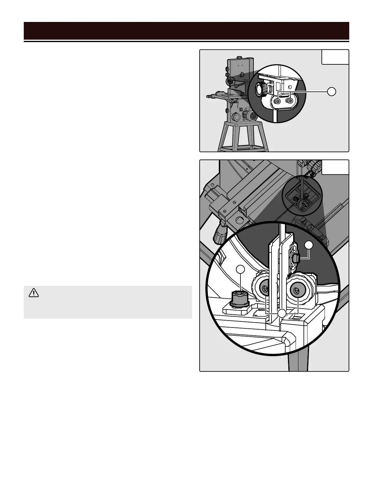
BEARINGS (FIG. 15 - 17)
3. Loosen the knob (Fig. 15 - B) on the left side of the upper
guide bearing assembly. Position the thrust bearing so that
it is as close to the spine of the blade as possible, without
touching it.
4. Rotate the blade a few times to ensure that the spine of
the blade does not touch the bearing at all while the blade
is rotating. Once the bearing has been properly positioned,
tighten the knob (Fig. 15 - B).
5. Use a hex wrench to loosen the socket-head cap screws
(C) on the back of the upper guide bearing assembly. Posi-
tion the roller bearings so that they are as close as possible
to the body of the blade without touching it. This will be
about 0.5 mm (1/50 inch).
6. Rotate the blade a few times to ensure that the body of
the blade does not touch either roller bearing at all while
the blade is rotating. Once the bearings have been properly
positioned, tighten the screws.
ADJUSTING THE LOWER GUIDE BEARINGS
(FIG. 18)
Proper adjustment of the guide bearings is one of the best
things you can do for your saw – it will prolong blade life,
prolong bearing life, and help prevent blade “drift”.
Fig. 18
Fig. 17
WARNING! The lower blade guide bearings must
be adjusted after every blade change and tracking
adjustment.
1. Turn off and unplug the band saw. Wait for the blade to
come to a complete stop. Open the lower door.
2. Use a hex wrench to loosen the socket-head cap screw
(D) found beneath the table insert. Position the assembly
so that the roller bearings are about 1 – 2 mm (1/10 inch)
behind the tooth gullets (Fig. 16). Tighten the screw.
3. Use a hex wrench to loosen the socket-head cap screw
(E) on the thrust bearing. Position the thrust bearing so
that it is as close to the spine of the blade as possible,
without touching it.
4. Rotate the blade a few times to ensure that the spine of
the blade does not touch the bearing at all while the blade
is rotating. Once the bearing has been properly positioned,
tighten the screw (E).
5. Use a hex wrench to loosen the socket-head cap
screws (F) on the roller bearings. Position the roller
bearings so that they are as close as possible to the
body of the blade without touching it. This will be
about 0.5 mm (1/50 inch).
6. Rotate the blade a few times to ensure that the
body of the blade does not touch either roller bearing
at all while the blade is rotating. Once the bearings
have been properly positioned, tighten the screws.
ASSEMBLY & ADJUSTMENTS
C
D
E
F