Fig. 13
ASSEMBLY & ADJUSTMENTS
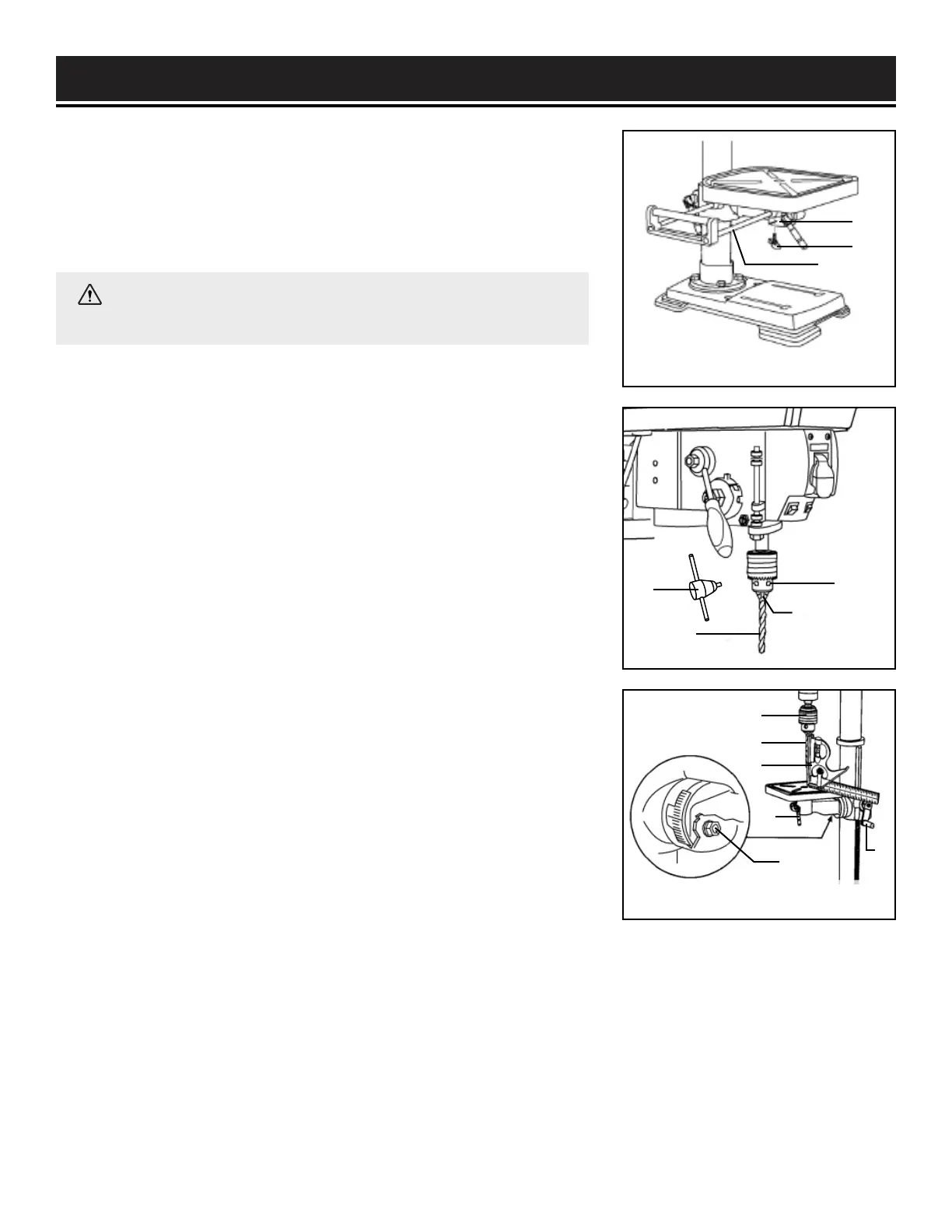
INSTALLING A DRILL BIT (FIG. 13)
1. Place the chuck key (Fig. 13 - 1) into the side keyhole of the chuck
(Fig. 13 - 2), meshing the key with the gear teeth.
2. Turn the chuck key counterclockwise to open the chuck jaws
(Fig. 13 - 3).
3. Insert a drill bit (Fig. 13 - 4) into the chuck far enough to obtain the
maximum grip of the chuck jaws on the bit shank.
4. Center the drill bit in the chuck jaws before the final tightening of
the chuck.
5. Tighten the chuck jaws using the chuck key to ensure that the drill
bit will not slip while drilling. Tighten all three keyholes on the chuck.
6. Remove the chuck key and place it back on the onboard storage.
15
Fig. 12B
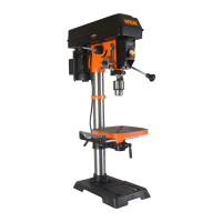
INSTALL THE TABLE EXTENSION (FIG. 12B)
1. Insert the two rods (Fig. 12B - 1) of the table extension into the
two channels (Fig. 12B - 2) at the side of the table.
2. Place a wing knob (Fig. 12B - 3) in the opening on the bottom of
each channel and tighten to secure the extension to the table.
SQUARING TABLE TO THE DRILL BIT (FIG. 14)
1. Insert a 3" long drill bit (Fig. 14 - 1) into the chuck (Fig. 14 - 2) and
tighten the jaws with the chuck key.
2. Raise the table with the crank handle (Fig. 14 - 3). Lock the table
(Fig. 14 - 4) approximately 1" below the drill bit.
3. Place a combination square (Fig. 15 - 5) (not included) on the
table as shown, placing the long straight edge of the combination
square against the drill bit. Make sure the drill bit is parallel / aligned
exactly to the straight edge of the square.
Fig. 14
1
2
3
1
2
3
4
1
2
3
4
5
6
WARNING: To avoid injury, make sure the chuck key is
removed from the chuck before starting any drilling operation.
4. If an adjustment is needed, loosen the bevel lock bolt (Fig. 14 - 6) with a wrench.
5. Tilt the table slightly, until the combination straight edge is aligned perfectly with the drill bit.
6. Tighten the bevel lock when square.
 Loading...