9
ASSEMBLY AND ADJUSTMENTS
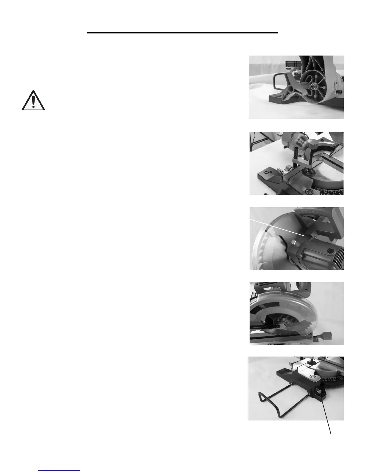
BEVEL LOCK
The bevel lock is used to set the blade at the desired bevel angle (FIGURE 5).
The miter saw bevels from 0° to 45° left only. Hold the operating handle and
loosen the bevel lock to set the bevel angle. Tighten the bevel lock.
WARNING: Be sure to tighten the bevel lock before making a cut.
Failure to do so could result in the saw arm moving during the cut
and cause serious personal injury.
HOLD DOWN CLAMP ASSEMBLY
The hold down clamp assembly can be mounted to the fence on either side
of the saw blade depending on what suits the task at hand. Use the clamp
assembly lock at the back of the fence to secure the clamp assembly in position
(FIGURE 6). Check that the clamp doesn’t interfere with the entire path of
the saw travel before operation.
SPINDLE LOCK BUTTON
The spindle lock button prevents the blade in the saw from rotating (FIGURE
7). Depress and hold the spindle lock button while installing, changing or
removing the blade.
ROTATING LOWER BLADE GUARD
The rotating lower blade guard provides protection from both sides of the
blade (FIGURE 8). It retracts over the upper blade guard as the saw is lowered
onto the workpiece.
DUST COLLECTION BAG
The dust collection bag fits over the dust extraction port. For more efficient
operation, empty the dust bag when it is half full. This allows better air flow
through the bag.
ATTACHING THE MATERIAL SUPPORT ARMS
The material support arms help to support the material when working with
long workpieces. There are two location holes for support bars on either side
of the table. Loosen the lock screws with the hex key. Ensure the side bars are
fully inserted before using them to support the workpiece (FIGURE 9).
The side support bar locking screws must be tightened to secure the support
bars in position.
FIGURE 5
FIGURE 6
FIGURE 7
FIGURE 8
FIGURE 9
(Lock Screws)
(Spindle Lock)
 Loading...