CONTROL
PANEL
-
EARLY
MODELS
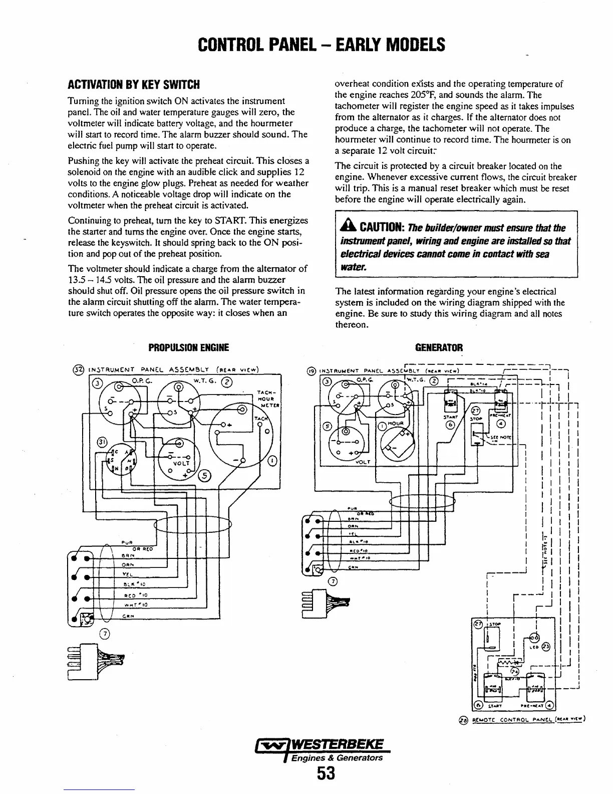
ACTIVATION
BY
KEY
SWITCH
Turning
the
ignition switch ON activates the instrument
panel. The oil and water temperature gauges will zero, the
voltmeter
will
indicate battery voltage, and the hourmeter
wi1l
start
to
record time. The alarm buzzer should
sound.
The
electric
fuel
pump will start
to
operate.
Pushing
the
key
wiJI
activate the preheat circuit.
This
closes
a
solenoid
on
the engine with an audible click and
supplies
12
volts
to
the
engine glow plugs. Preheat as needed for
weather
conditions. A noticeable voltage drop will indicate on
the
voltmeter when the preheat circuit is activated.
Continuing
to
preheat, tum the
key
to START.
This
energizes
the starter and turns the engine over.
Once the engine starts,
release the keyswitch.
It should spring back to the
ON
posi-
tion and pop out
of
the preheat position.
The
voltmeter should indicate a charge from the alternator
of
13.5 -
14.5
volts. The oil pressure and the alarm
buzzer
should shut off. Oil pressure opens the-oil pressure
switch
in
the aJann circuit shutting off the alarm.
The
water tempera-
ture switch operates the opposite way:
it
closes when
an
PROPULSION
ENGINE
overheat condition ex-ists and the operating temperature
of
the engine reaches 205°F, and sounds the alarm. The
tachometer will register the engine speed as
it
takes impulses
from the alternator as
it
charges. If the alternator does
not
produce a charge, the tachometer will not operate. The
hourmeter will continue to record time. The hourmeter
is
on
a separate 12 volt
circuit:'
The
circuit
is
protected by a circuit breaker located
on
the
engine. Whenever excessive current flows, the circuit breaker
will trip. This is a manual reset breaker which must
be
reset
before the engine
wiJI
operate electrically again.
A
CAUTION:
The
builder/owner
must
ensure
that
the
instrument
panel,
Wiring
and
engine
are
installed
so
that
electrical
devices
cannot
come
in
contact
with
sea
water.
The
latest infonnation regarding your engine's electrical
system is included on the wiring diagram shipped with the
engine. Be sure to study this wiring diagram and all notes
thereon.
GENERATOR
r-------
-
----
--i
@
IN~TAvweNT
PANeL
A!)SC"'Sl.'Y
( .. (
........
e .. )
,----1--1
0.1".<:.
"':1'.
G..
Ii'
r-
- - - I
--
--,
I
Aeo
·,0
G
....
.,.....;:::\V:::..--4--_:::..~::..~
'.:.;:.'"
--,
,f
,... - - - -
1--1"'1
I
""O--+-4-10.......Q...1_
-cr'
• " I I I I
,..----II~I-I-
- -
~
-,-:--
--rl
Engines & Generators
53
....,
I
I
I
I
I
I
I
,
I
I
I
I
I
I
I
I I
'I
I I
'I
I \ I I
I I I I
I
I I I
I I I
il
: I
I I I I
I I I I
I I
:1
I~
I
I:
Ii
II
I I
I:;
I I I I
r I I I I
I I I I I
r
--.-I
I I I I
-1
I I I
r I I
..--+----+-....Jo.-...,
I I I
I I I
I I I
I I !
I J I
1-
I
I
I
__
J