ALTERNATOR/REGULATOR
SERVICE
The
voltage
reading
for a properly operating alternator
should be between 13.5 and 14.5 volts.
If your alternator is
over-
or
undercharging, have
it
repaired at a reliable service
shop,
or
continue
with
the following tests.
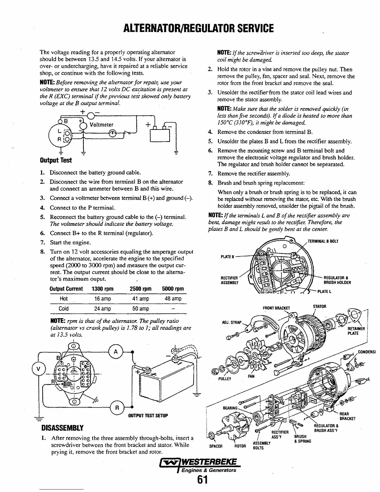
NOTE:
Before removing the alternator for
repair,
use your
voltmeter to ensure that
I2
volts
DC
excitation is preselll at
the R (£XC) terminal
if
the previous tesi showed only battery
voltage at the B output terminal.
+
Output
Test
1. Disconnect the battery ground cable.
2. Disconnect the
wire
from terminal B on the alternator
and
connect
an
ammeter
between B and this wire.
3.
Connect a voltmeter between terminal B (+) and ground
(-).
4.
Connect to the P terminal.
5.
Reconnect the battery ground
cable
to the
(-)
tenninal.
The voltmeter
should
indicate the battery voltage.
6.
Connect
B+
to the R terminal (regulator).
7.
Start the engine.
S.
Tum
on
12
volt
accessories equaling the
amperage
output
of
the alternator, accelerate the engine to the specified
speed
(2000
to
3000
rpm) and measure the output cur-
rent.
The
output
current should
be
close to the alterna-
tor's
maximum
ouput.
Output
Current 1300
rpm
2500
rpm
5000
rpm
Hot
16
amp
41
amp
48
amp
Cold
24
amp
50
amp
NOTE:
rpm is thaI
of
the alternator. The pulley ratio
(alternator vs crank pulley)
is
1.78 to 1; all readings are
at
j 3.5 liolts.
OUTPUT
TEST
SETUP
DISASSEMBLY
1.
After
removing
the three assembly through-bolts, insert a
screwdriver
between
the front bracket and stator. While
prying it,
remove
the front bracket and rotor.
NOTE:
If
the screwariver
is
inserted too deep, the slOtor
coil might be damaged.
2. Hold the rotor
in
a vise and remove the pulley nut.
Then
remove the pulley, fan, spacer and seal. Next, remove the
rotor from the front bracket and remove the seal.
3.
Unsolder the rectifierfrom the stator coil lead wires and
remove the stator assembly.
NOTE:
Make sure that
the
solder is removed quickly (in
less
than
five seconds).
If
a diode is heated to more than
I50
a
C (310°F), it might
be
damaged.
4. Remove the condenser from terminal B.
5. Unsolder the plates
Band
L from the rectifier assembly.
6. Remove the mounting screw and B terminal bolt and
remove the electronic voltage regulator and brush holder.
The
regulator and brush holder cannot be sepearated.
7. Remove the rectifier assembly.
S. Brush and brush spring replacement:
When only a brush or brush spring is to be replaced,
it
can
be
replaced without removing the stator, etc. With the brush
holder assembly removed, unsolder the pigtail
of
the brush.
NOTE:
If
the terminals
Land
B
of
the rectifier assembly are
bent,
damage might result to the rectifier. Therefore, the
plates
Band
L should
be
gently bent
at
the center.
RECTIFIER
ASSEMBLY
SPACER
ROTOR
TERMINAL
B
BOLT
REGULATOR
&
BRUSH
HOLDER
STATOR
........
REAR
BRACKET
Engines & Generators
61