Operator Manual for Gasoline Generators 5 Maintenance
page 35
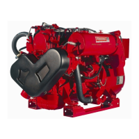
5.5.5 Shore Power Transfer Switch
If the installer connects shore power to the AC circuit on your vessel, this must be done by means of a shore
power transfer switch. Ship-to-shore switches are available from Westerbeke or an authorized dealer.
Figure 29: Shore Power Transfer Switch
Set the transfer switch shown in the diagram to the OFF position. This switch prevents simultaneous
connection of shore power to generator output.
Observe the following precautions before switching from shore power to generator power:
CAUTION: Heavy motor leads should be shut off before switching shore power to generator power or vice-versa
because voltage surges Induced by switching with heavy AC loads on the vessel being operated may cause damage to
the exciter circuit components in the generator.
CAUTION: Damage to the generator can result if utility shore power and generator output are connected at the same
time. This type of generator damage is not covered under warranty; it is the responsibility of the installer to make sure all
AC connections are correct.
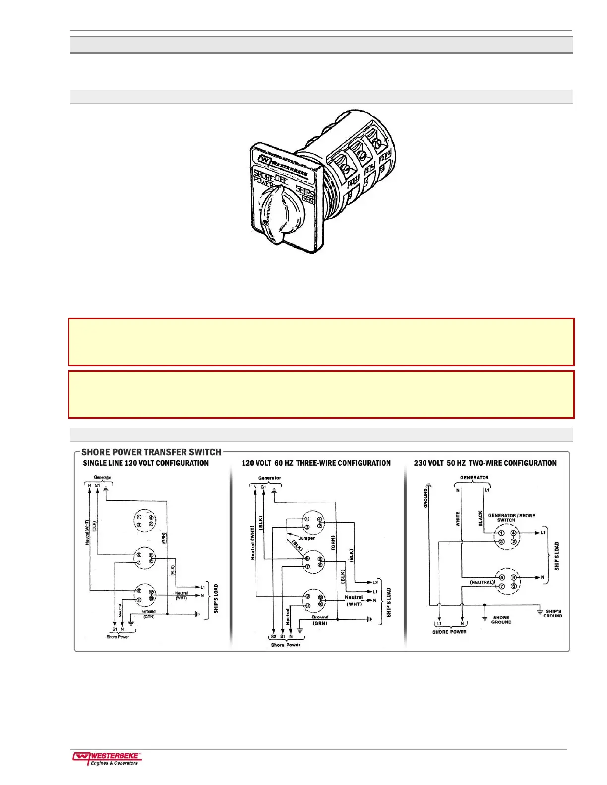
Figure 30: Shore Power Transfer Switch Configurations
The second configuration shows connections for a two-wire 120-volt system from the generator with a three-
wire 120-volt boat system. In the second and third configurations, notice the repositioning of the white wire
ground load on the terminal block to the generator case. No 240-volt equipment is permitted in the ship’s
load for the first and second configurations.
 Loading...