Cooling System
The
generator's engine
is
fresh water cooled by
an
engine-mounted heat exchanger.
Sea
water
is
used
as
the heat exchanger's cooling
medium.
Sea
water
is
pumped through the heat exchanger by a belt-driven,
positive displacement rubber impeller
pump.
Afterthe
sea
COOLANTIIECOVEJIYTAIIIC
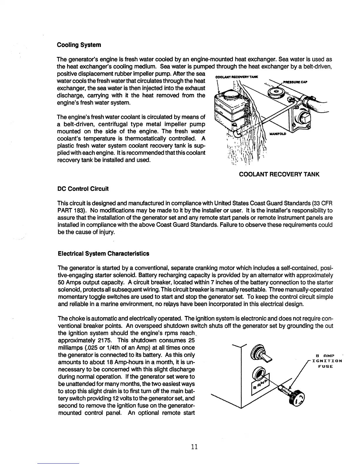
water cools the fresh water that circulates through the heat
exchanger, the
sea
water
is
then injected into the exhaust
discharge, carrying with it the heat
removed
from the
engine's fresh water
system.
The
engine's fresh water coolant
is
circulated by
means
of
a belt-driven, centrifugal type metal impeller pump
mounted
on
the side of the engine. The fresh water
coolant's temperature
is
thermostatically controlled. A
plastic fresh water system coolant recovery tank is sup-
plied with
each
engine.
It
is
recommended thatthis coolant
recovery tank
be
installed
and
used.
DC Control Circuit
COOLANT
RECOVERY
TANK
This circuit
is
designed
and
manufactured
in
compliance with United States Coast
Guard
Standards
(33
CFR
PART
183).
No modifications
may
be
made
to it by the installer or
user.
It
is
the installer's responsibility to
assure that the installation of the generator set
and
any remote start panels or remote instrument
panels
are
installed
in
compliance with the above Coast
Guard
Standards. Failure to observe these requirements could
be
the cause of injury.
Electrical System Characteristics
The
generator
is
started by a conventional,
separate
cranking motor which includes a self-contained, posi-
tive-engaging starter solenoid. Battery recharging capacity
is
provided by
an
alternator with approximately
50
Amps output capacity. A circuit
breaker,
located within 7 inches of the battery connection to the starter
solenoid, protects
all
subsequent wiring.
This
circuit breaker
is
manually resettable.
Three
manually-operated
momentary toggle switches are
used
to start
and
stop the generator
set.
To
keep
the control circuit simple
and
reliable
in
a marine environment, no
relays
have
been
incorporated
in
this electrical design.
The
choke
is
automatic
and
electrically operated.
The
ignition system
is
electronic
and
does not
require
con-
ventional breaker points.
An
overspeed shutdown switch shuts off the generator set by grounding the out
the ignition system should the engine's
rpms
reach,
approximately
2175.
This shutdown consumes
25
milliamps
(.025
or 1/4th of
an
Amp)
at
all
times once
the generator
is
connected
to
its battery.
As
this only
amounts to about
18
Amp-hours
in
a month, it
is
un-
necessary to
be
concerned with this slight discharge
during normal operation.
If the generator
set
were
to
be
unattended for many months, the two
easiest
ways
to stop this slight drain
is
to first turn off the
main
bat-
tery switch providing
12
volts to the generator
set,
and
second
to
remove
the ignition
fuse
on
the generator-
mounted control
panel.
An
optional remote start
11
B AMP
IGNITION
FUSE
 Loading...