EasyManua.ls Logo

Westerbeke 6.5KW - Page 48

Westerbeke 6.5KW
125 pages
Print Icon
To Next Page IconTo Next Page
To Previous Page IconTo Previous Page
Loading...
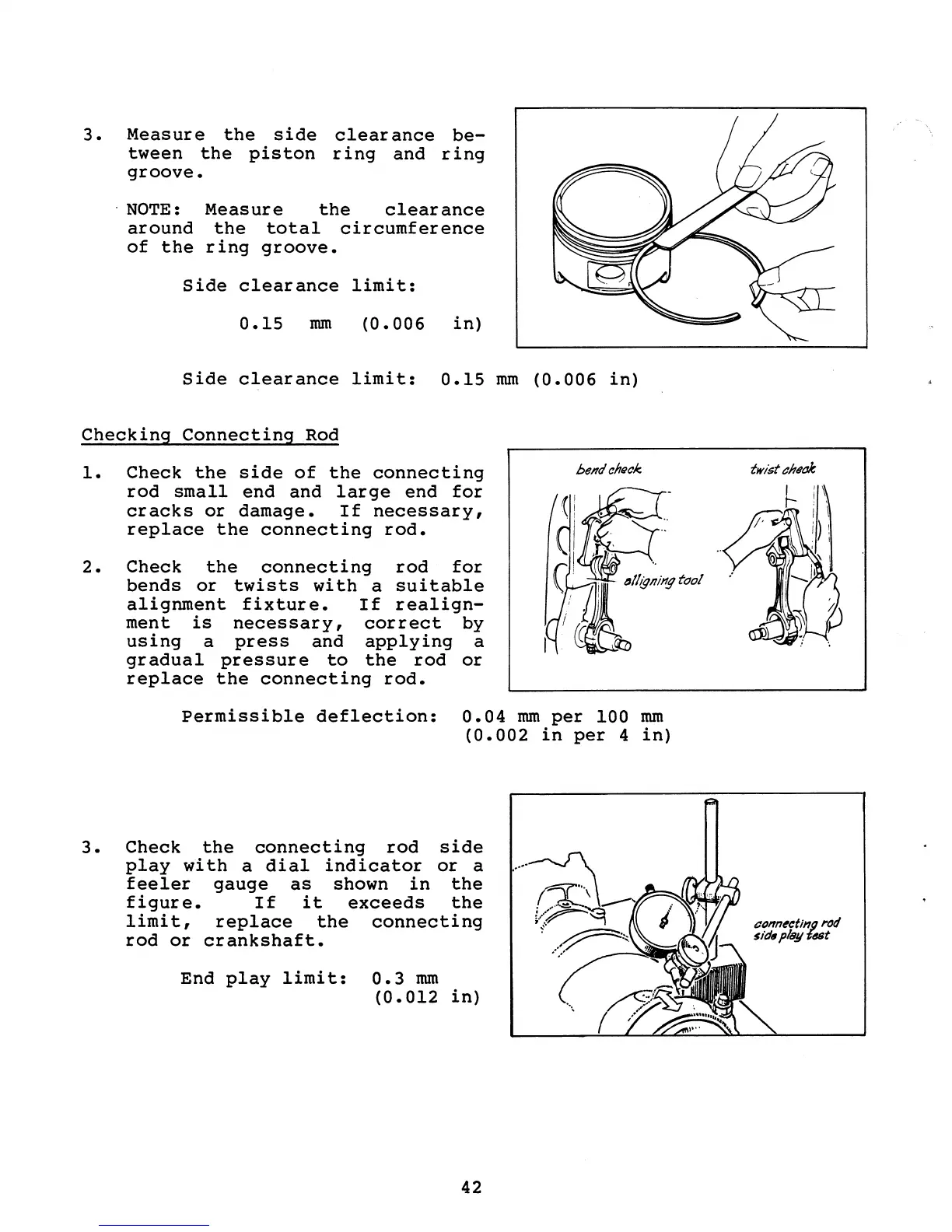
3.
Measure
the
side
clearance
be-
tween
the
piston
ring
and
ring
groove
. NOTE:
Measure
the
clearance
around
the
total
circumference
of
the
ring
groove.
Side
clearance
limit:
0.15
mm
(0.006
in)
Side
clearance
limit:
0.15
mm
(0.006
in)
Checking
Connecting
Rod
1.
Check
the
side
of
the
connecting
rod
small
end
and
large
end
for
cracks
or
damage.
If
necessary,
replace
the
connecting
rod.
2.
Check
the
connecting
rod
for
bends
or
twists
with
a
suitable
alignment
fixture.
If
realign-
ment
is
necessary,
correct
by
using
a
press
and
applying
a
gradual
pressure
to
the
rod
or
replace
the
connecting
rod.
Permissible
deflection:
0.04
mm
per
100
mm
(0.002
in
per
4
in)
3.
Check
the
connecting
rod
side
play
with
a
dial
indicator
or
a
feeler
gauge
as
shown
in
the
figure.
If
it
exceeds
the
limit,
replace
the
connecting
rod
or
crankshaft.
End
play
limit:
0.3
mm
(0.012
in)
42
twist
t:h"a/e
~