Operator Manual for Gasoline Generators 5 Maintenance
page 33
Capacitor and repulsion-induction motors require from two (2) to four (4) times as much current to start as to
run. The current required to start any motor varies with the load connected to it. An electric motor connected
to an air compressor, for example, will require more current than a motor to which no load is connected.
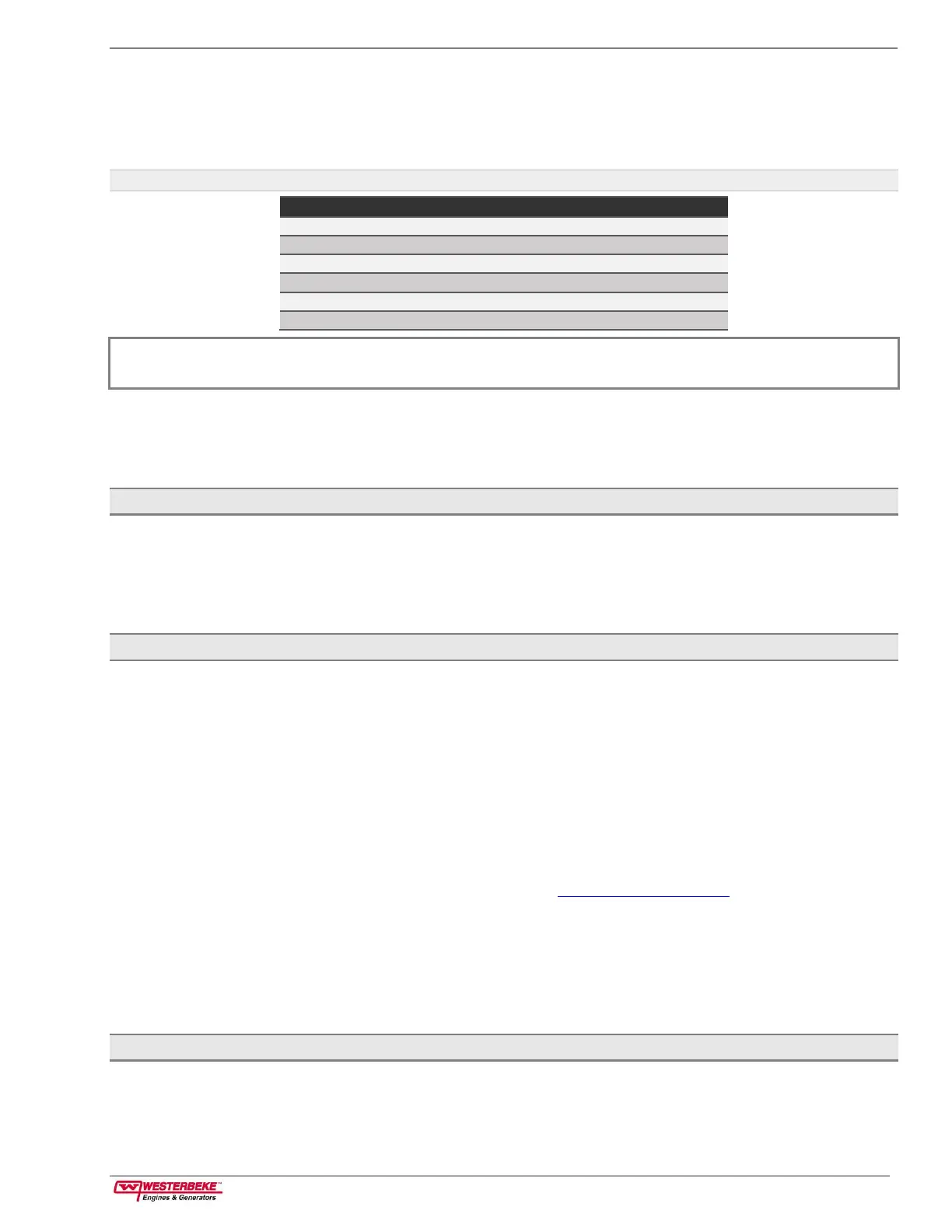
The following table shows the approximate current required to start a 115-volt motor connected to a medium
starting load:
Table 3: Electric Motor Starting and Running Current Requirements
NOTE: The maximum AMPS TO START is greater for some smaller motors than for larger ones because the hardest
starting types (split-phase) are not manufactured in larger sizes.
Because the heavy surge of current needed for starting motors is required for only a brief period, the
generator will not be damaged if it can bring the motor up to speed quickly. If difficulty is experienced in
starting motors, turn off all other electrical loads and, if possible, reduce the load on the electric motor. Some
motor controllers can be configured to reduce the peak starting current. These are called soft-start controls.
5.5.2 Load Test
1.
Run the generator with no load applied.
2.
Run the generator at half capacity.
3.
Run the generator loaded to its full capacity as indicated on the generator data plate.
4.
Periodically check the output voltage to ensure proper operation of the generating plant and the appliances
it supplies. Monitor voltage and load with a portable meter and amp probe.
5.5.3 BC Generator Single Phase
The BC generator is a brushless, self-excited generator which requires only the driving force of the engine to
produce an AC output. The stator houses three groups of windings: the main stator windings, the exciter
windings, and battery charge winding.
When the generator is started, residual magnetism in the four rotating poles induces a current in the stator
which then generates an even larger current in the exciter windings. This mutual buildup of current in the four
rotating poles and in the exciter windings quickly reaches the saturation point of the capacitor(s) and a
regulated energy field is then maintained in the stator. At the same time, this regulated field produces a steady
voltage in the stator windings which can then be drawn off the generator AC terminals to operate AC
equipment.
The generator is a single-phase, reconnectable 120-volt AC two-wire at 60 Hertz or 115-volt AC two-wire or
230 volt or AC two-wire, at 50 Hertz. For generator ratings, see Generator Specifications toward the end of this
manual.
The generator data plate gives the normal voltage, current, and frequency rating of the generator. An AC
wiring decal is affixed on the inside of the control box cover. It has diagrams of the various AC output wiring
configurations. A Battery Charge Controller is mounted on the outside of the control box adjacent to the AC
circuit breaker and supplies a continuous DC charge to the generator’s dedicated starting battery when the
generator is operating.
5.5.4 AC Circuit Breaker
A circuit breaker is installed on all single-phase Westerbeke generators. This circuit breaker will automatically
disconnect generator power in case of an electrical overload. The circuit breaker can be manually shut off
when servicing the generator to ensure that no power is being supplied into the boat.
 Loading...