EasyManuals Logo

Westermo Lynx SERIES User Manual

Westermo Lynx SERIES
32 pages
To Next Page IconTo Next Page
To Previous Page IconTo Previous Page
Page #13 background imageLoading...
Page #13 background image
3
2
1
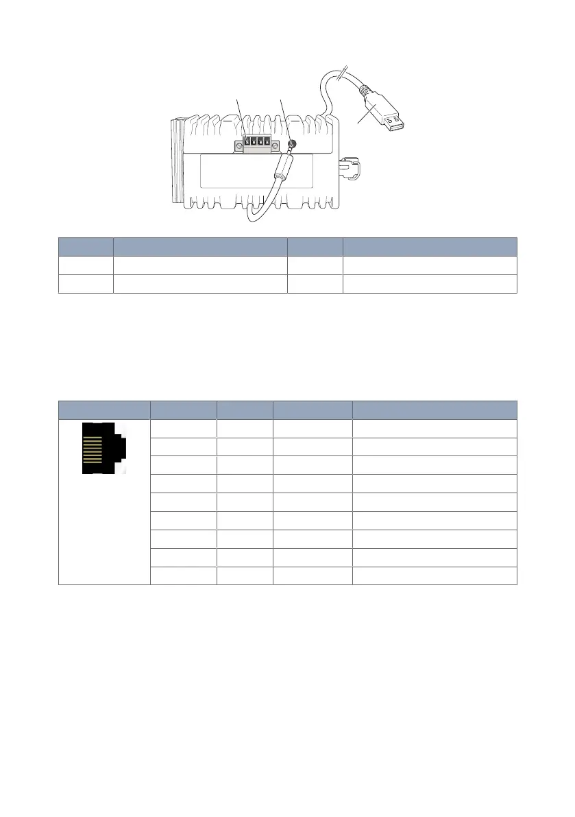
No. Description No. Description
1 I/O connection 2 Console port
3 Accessorie cable, art. no. 1211-2027
Figure 4. Location of interface ports, bottom view
3.4. Connector Information
3.4.1. Ethernet Connection TX
Illustration
Pin no. Signal Direction Description
1 TD+ In/Out Transmitted/Received data
2 TD- In/Out Transmitted/Received data
3 RD+ In/Out Transmitted/Received data
4 - - Not connected
5 - - Not connected
6 RD- In/Out Transmitted/Received data
7 - - Not connected
8 - - Not connected
Shield Connected to PE
Table 6. Ethernet connection TX
Lynx L110-F2G & L210-F2G 13

Questions and Answers:

Question and Answer IconNeed help?

Do you have a question about the Westermo Lynx SERIES and is the answer not in the manual?

Westermo Lynx SERIES Specifications

General IconGeneral
ModelLynx SERIES
ManagementWeb interface, CLI, SNMP
Operating Temperature-40°C to +70°C
MountingDIN-rail
DimensionsVaries depending on model
WeightVaries depending on model
StandardsIEEE 802.3
CategoryIndustrial Ethernet Switch

Related product manuals