26 | English
MAINTENANCE
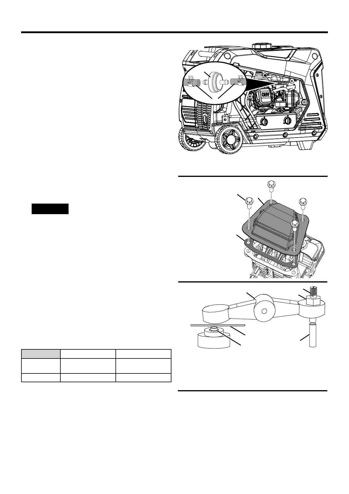
REPLACING THE FUEL FILTER
See Figure 26.
Overtime, the fuel lter may become dirty or clogged. To
reduce the risk of engine failure, replace the fuel lter ac-
cording to the gures specied in the maintenance schedule
or the engine manual (if applicable).
l Turn the generator off and allow the engine to cool for
30minutes.
l Drain the fuel tank as described previously.
l Remove the engine service cover.
l Locate the fuel lter and note the lter’s orientation.
l Using pliers, squeeze the fuel line clips and slide the fuel
lines away from the lter.
l Install the fuel lines onto the new lter. Make sure the fuel
lter is oriented correctly.
l Replace the engine service cover and tighten screws
securely.
CHECKING/ADJUSTING THE VALVE
CLEARANCE
See Figures 27 - 28.
NOTICE
Checking and adjusting valve clear-
ance must be done when the engine is cold.
l Turn the generator off and allow the engine to cool for
30minutes.
l Place the generator on a level surface in a well-ventilated
area.
l Remove the rocker arm cover and carefully remove the
gasket. If the gasket is torn or damaged, it must be re-
placed.
l Remove the spark plug so the engine can be rotated more
easily.
l Pull the recoil handle to rotate the engine to top dead
center (TDC). Looking through the spark plug hole; the
piston should be at the top (both valves are closed).
l Both rocker arms should be loose at TDC on the com-
pression stroke. If they are not, rotate the engine 360°.
l Insert a feeler gauge between the rocker arm and the
valve stem to measure valve clearance.
Intake Valve Exhaust Valve
Valve
Clearance
0.0031 – 0.0047 in
(0.08 – 0.12 mm)
0.005 – 0.007 in
(0.13 – 0.17 mm)
Torque 8 –12 Nm 8 –12 Nm
l If an adjustment is necessary, loosen the jam nut.
l Slide the appropriate feeler gauge between the rocker
arm and the valve stem.
l Tighten the adjustment screw onto the push rod to obtain
the specied clearance.
NOTE: You should be able to feel the rocker arm touch
the feeler gauge.
l Hold the adjustment screw in place and tighten the nut.
A - Fuel line
B - Fuel filter
A
B
FIG. 26
Torque: 106 inch-pound (12 Nm)
l Recheck valve clearance.
l If no further adjustments are needed, perform this proce-
dure on the other valve.
l When nished, install the gasket, rocker arm cover, and
spark plug.
FIG. 27
FIG. 28
A - Adjustment screw
B - Jam nut
C - Feeler gauge
D - Rocker arm
E - Valve stem
F - Push rod
B
C
A
B
A
D
C
E
F
A - Rocker arm cover
B - Bolt
C - Gasket