For Service Technician Use Only
DIAGNOSTICS
1-14
n
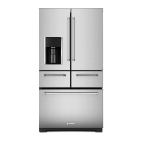
French-Door Boom Mount Refrigerator
Air Flow System
The air ow system is composed of ducng and a number of
fans to provide air ow to the four temperature controlled zones
located in the RC and FC Compartments. Proper air ow allows
ecient removal of heat and uniform temperature distribuon in
each zone.
The air ow system also provides air ow in the machine
compartment, cooling equipment and removing waste heat from
the condenser.
All fans are supplied with a constant 12.7 VDC power from the
Orion board, P16-4. The fans are switched On, when necessary,
by a separate 12.7 VDC signal provided from the GF2 board.
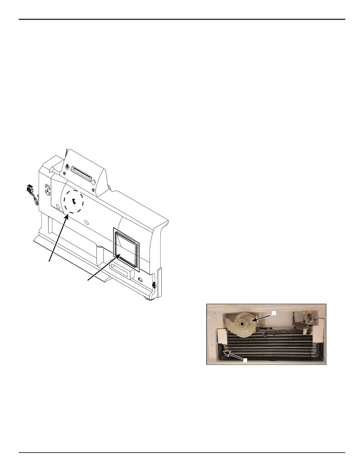
The RC evaporator fan and the pantry air bae are located in the
evaporator cover assembly in the RC. They control airow to the
two temperature controlled zones, the RC and the pantry.
The RC evaporator fan is a variable speed fan. It moves RC air
over the evaporator to remove heat from the RC.
The RC evaporator fan is supplied with constant 12.7 VDC power
from Orion board P16-4. The fan is switched On and O by a
12.7 VDC gang signal from GF2 board P14-3. The gang signal
is adjusted based on temperature to change the speed of the fan
between HI (3450 rpm) and LOW (1725 rpm).
The RC fan is switched On any me the refrigeraon system is
cooling the RC. The RC fan will run for a period of me following
cooling, and then be switched o. If the refrigerator is in pull
down mode, the RC fan will run for an addional 20 minutes
aer compleon of RC cooling.
If the RC evaporator needs defrosng, the RC fan may run for up
to 10 addional minutes aer RC cooling.
The pantry is the second temperature controlled zone cooled by
the RC evaporator. The pantry is cooled by airow from the RC
fan directed through foam ducng in the RC evaporator cover
assembly. The pantry air bae is either full open, or full close
dependent upon pantry temperature.
The pantry is operated by 115 VAC power supplied from GF2
board P2-5. 115 VAC power is also supplied to a feedback switch
by GF2 board P2-2, providing the board with posion indicaon
for the pantry air bae.
The pantry air bae will open when:
• Pantry requests cooling.
• RC is cooling.
The pantry air bae will be CLOSED at all other mes.
The FC evaporator fan and the ice box fan are located in the FC.
They control airow to the two temperature controlled zones,
the FC and the ice box.
The FC evaporator fan is a variable speed fan. It moves FC air
over the evaporator to remove heat from the FC.
The FC evaporator fan is supplied with constant 12.7 VDC power
from Orion board P16-4. The fan is switched On and O by a
12.7 VDC gang signal from GF2 board P14-1. The gang signal
is adjusted based on temperature to change the speed of the fan
between HI (3450 rpm) and LOW (1725 rpm).
The FC fan is switched On any me the refrigeraon system is
cooling the FC. The FC fan will run for an addional 2 minutes
aer compleon of FC cooling. The FC fan will also run an
addional 2 minutes aer compleon of cooling while the
refrigerator is in Pull Down Mode.
The IB Fan is a variable speed fan located in the FC. It circulates
air from the FC Evaporator area to the IB in the le RC door to
maintain temperature at its set-point. For models with an ice
maker in the FC, it also circulates air over the FC ice maker.
The IB fan is supplied with constant 12.7 VDC power from Orion
board P16-4. The fan is switched On and O by a 12.7 VDC gang
signal from GF2 board P9-2. The gang signal is adjusted based
on temperature to change the speed of the fan between HI
(3450 rpm) and LOW (1725 rpm).
The IB fan is On any me the FC fan is On. The IB Fan is O when
the FC fan is O.
Air Baffle
Location
RC Fan Location
B
A
A. IB Fan
B. IB Air Duct Return