For Service Technician Use Only
DIAGNOSTICS
1-18
n
French-Door Boom Mount Refrigerator
Defrost and Moisture Control
The defrost system is designed to remove ice build-up from the
Refrigerator Compartment (RC) and Freezer Compartment (FC)
evaporators when required. FC defrost is accomplished using
a heater, while RC defrost is accomplished using the relavely
warm air of the RC. The moisture control system uses heaters to
warm areas suscepble to condensaon.
The FC Evaporator is defrosted as necessary to remove frost
or ice buildup. Defrost is accomplished with a 115 VAC, 470 W
heater.
An Adapve Defrost Control (ADC) roune determines when a
defrost cycle is needed. ADC monitors Compressor operaon,
and the number of mes the FC door is opened are the primary
inputs to the ADC roune.
During defrost, 115 VAC power is applied to the heater from
GF2 board P2-7. The FC Evaporator Thermistor monitors the
temperature during defrost. When the FC Evaporator Thermistor
reads 50°F (10°C), defrost is ended by removing the 115 VAC
power from GF2 board P2-7.
There are two thermal fuses wired in series with the defrost
heater. The thermal fuses are designed to interrupt the defrost
cycle if the normal method does not funcon properly. The
thermal fuses open at 183°F (84°C), interrupng power to the
heater.
The RC Evaporator is defrosted at the end of each RC cooling
cycle. The RC Evaporator Fan runs for a period of me aer the
compleon of RC cooling. This defrosts the evaporator using the
relavely warmer air of the RC.
The fan runs unl the temperature dierenal between the RC
Evaporator Thermistor and the RC Air Thermistor is less than
1°F (-17°C). The fan will run for a maximum of 10 minutes, aer
which it shuts o, regardless of the temperature dierenal
between the thermistors.
The RC Evaporator is defrosted as necessary to remove frost
or ice buildup. Defrost is accomplished with a 115 VAC, 470 W
heater. An Adapve Defrost Control (ADC) roune determines
when a defrost cycle is needed. ADC monitors Compressor
operaon, and the number of mes the FC door is opened are
the primary inputs to the ADC roune.
During defrost, 115 VAC power is applied to the heater from
GF2 board P2-5. The FC Evaporator Thermistor monitors the
temperature during defrost. When the RC Evaporator Thermistor
reads 50°F (10°C), defrost is ended by removing the 115 VAC
power from GF2 board P2-5.
There is one thermal fuses wired in series with the defrost
heater. The thermal fuse are designed to interrupt the defrost
cycle if the normal method does not funcon properly. The
thermal fuses open at 183°F (84°C), interrupng power to the
heater.
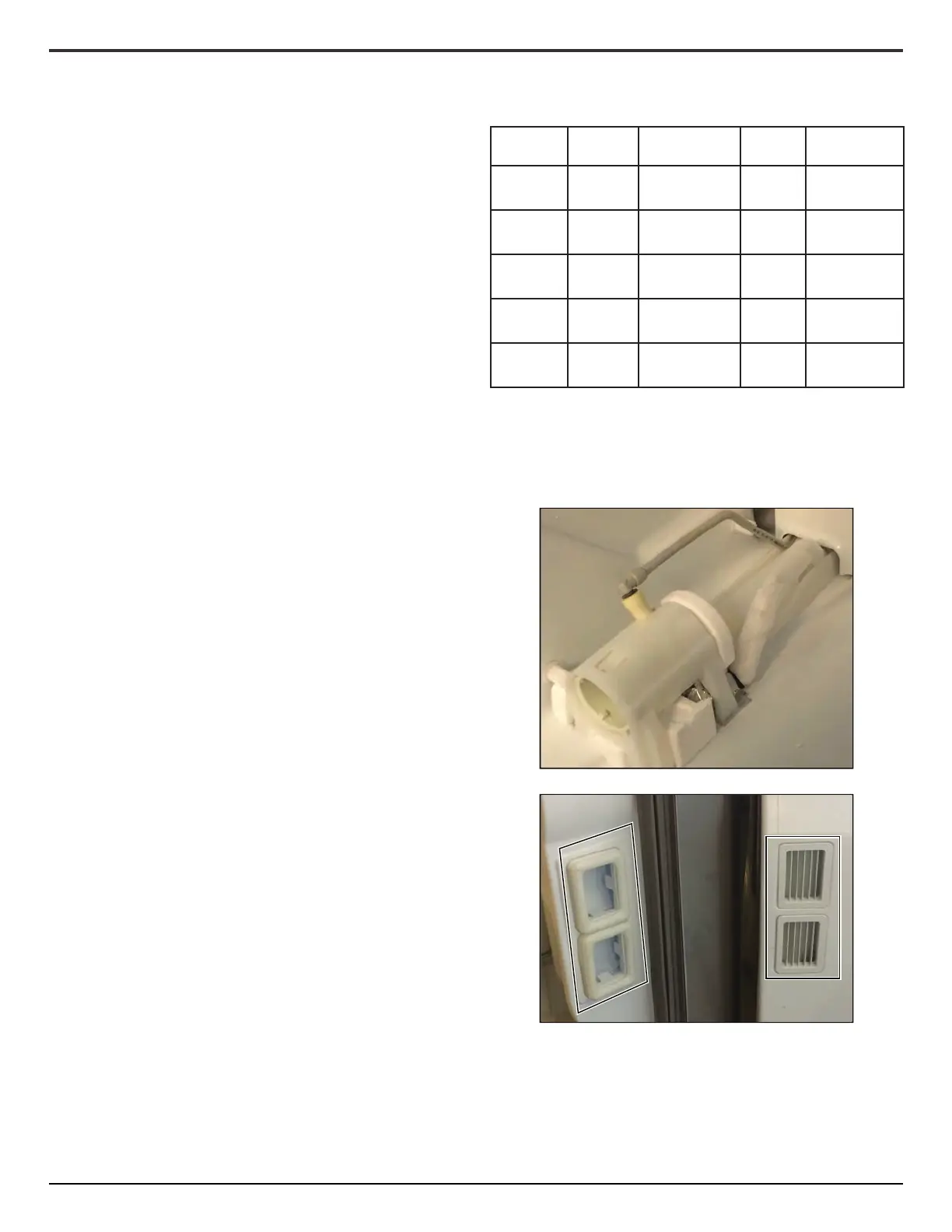
Heater Voltage
Voltage
Source
Watts Resistance
Filter 115 VAC
GF2 board
P2-6
3 4800
IB Duct
(Cabinet)
115 VAC
GF2 board
P2-6
5.5 2375
Dispenser 12.7 VDC
Dispenser UI
J8-1
1.5 108
IB Duct
(Door)
12.7 VDC
Dispenser UI
J8-1
1.5 108
Mullion 14 VDC
Door UI
J2-3
11.5 17
The refrigerator has heaters in necessary locaons to prevent
condensaon. The heaters can be operated in one of two
acvaon modes. The default mode is for the heaters to cycle in
response to measured humidity. Humidity is measured by a
sensor located on the Main control.