For Service Technician Use Only
DIAGNOSTICS
French-Door Boom Mount Refrigerator
n
1-15
Water and Ice System
The water and ice system receives household supplied water,
lters the water, and makes it available to the water dispenser,
in-door ice maker, and on some models, a second ice maker in
the freezer.
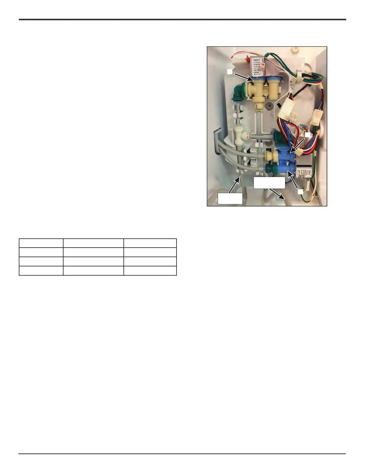
Water is supplied into the refrigerator through an isolaon valve,
directed to a water tank, then ltered and sent to the dual valve
controlling water ow to the water dispenser and Ice Maker.
On models with a freezer ice maker, ltered water is sent to a ‘T’
ng which directs water to the dual valve, and a second single
valve for the freezer ice maker.
The isolaon valve is located in the machine compartment on
the right rail. The valve is normally closed. The valve only opens
when water is being provided to the water dispenser, or either
ice maker.
The valve is opened by 115 VAC power supplied from GF2 board,
P12-4.
The outlet of the water reservoir is directed to the water lter.
The water lter is located behind the water lter door at the
front le boom of the RC.
The water lter supply line, and the rear of the water lter
housing are heated to prevent condensaon and freezing.
The dispenser UI tracks water dispensed and age of the lter
providing water lter indicaon on the dispenser UI. Water lter
indicaon informaon is given in below table.
Indicator Gallons Dispensed Filter Age (Days)
No Indicator 0 - 160 0 - 144
“Order Filter” 161 - 200 145 - 180
“Replace Filter” >200 >180
The water lter outlet is directed to the dual valve. The dual
valve directs the water supply to the water dispenser, or in-door
ice maker through individual valves.
The water lter outlet is directed to a ‘T’ ng. The ‘T’ ng
directs water to the dual valve and to the freezer ice maker ll
valve.
The Dispenser UI is responsible for dispensing water to the in-
water dispenser. The GF2 board controls water dispensing to the
in-door ice maker, and freezer ice maker (some models).
The dispenser is controlled by the front paddle of a stacked dual
paddle, or by the measured ll feature available on the dispenser
UI.
When water is requested the dispenser UI sends the request to
the GF2 board, which opens the isolaon valve. The dispenser UI
opens the low voltage Water Valve.
The GF2 board supplies 115 VAC to GF2 board, P12-4, opening
the isolaon valve.
The dispenser UI supplies 11.5 VDC dispenser UI, J8-5, opening
the water valve and dispensing water.
The dispenser UI controls all aspects of the in-door ice maker,
including the Fill Cycle. The ice maker Fill Cycle is 10 seconds,
lling the ice tray with about 3.2 oz. (100 ml) of water.
During a Fill Cycle, the Dispenser UI communicates to the GF2
board. The GF2 board supplies 115 VAC to P12-4, opening
the Isolaon Valve. At the same me, the GF2 board supplies
115 VAC to P3-3, opening the Water Valve for the In-Door Ice
Maker.
Aer 10 seconds, the Dispenser UI instructs the GF2 board to end
the Fill Cycle, the GF2 board removes power to the valve, ending
the Fill Cycle.
The Freezer Ice Maker is controlled by the GF2 board. This Fill
cycle is 10 Seconds, lling the ice tray with about 3.2 oz. (100ml)
of water.
A
From Water
Filter
From Reservoir
to Water Filter
B
C
A. Freezer IM Valve
B. ID IM Valve
C. Water Valve