For Service Technician Use Only
DIAGNOSTICS
1-22
n
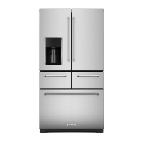
French-Door Boom Mount Refrigerator
• When entering service test, the numeric display shows the
current Heater Acvaon mode.
• “00” indicates mullion heater controlled by measured
humidity.
• “01” indicates mullion heater always on.
• To advance between control mode use “+” or “-” key. Once
desired seng is selected, push “Drawer” key to acvate,
then “Max Cool” to exit this mode.
• When entering service test, the numeric display shows the
current Heater Acvaon mode.
• “00” indicates dispenser heater controlled by measured
humidity.
• “01” indicates dispenser heater always ON.
• To advance between control mode, use “+” or “-” key. Once
desired seng is selected, push “Drawer” key to acvate then
“Max Cool” to exit this mode.
• When entering service test, the numeric display shows the
current Heater Acvaon mode.
• “00” indicates dispenser heater controlled by cooling
performance.
• “01” indicates dispenser heater always ON.
• To advance between control mode use “+” or “-” key. Once
desired seng is selected, push “Drawer” key to acvate then
“Max Cool” to exit this mode.
• When entering this service test, defrost heater turns on and
stays on for 5 minutes or unl the evaporator thermistor goes
above 60°F (15.5°C).
• “ON” will be displayed while the operaon is executed.
• When entering this service test, defrost heater turns on and
stays on for 5 minutes or unl the evaporator thermistor goes
above 60°F (15.5°C).
• “ON” will be displayed while the operaon is executed.
• Acvates the forced defrost.
• When “ON” is selected and exing Service mode, defrost will
be executed.
• When “OFF” is selected and exing Service mode, defrost will
NOT be executed. To advance between control mode “ON”
or “OFF” Use “+” or “-” key. Once desired seng is selected,
push “Drawer” key to acvate then “Max Cool” to exit this
mode.
• When entering service test all indicators and buons will light
up in the two UIs.
• The icons automacally turn o aer 30 seconds.
• When inside service test, the numeric display shows “00” for
no key press and “01” for key or pad pressing.
• When entering service test, the Water Dispenser Valve turns
on for 7 seconds.
• When entering service test, the Door Ice Maker Water Valve
turns on for 7 seconds.
• When entering service test, the Door Ice Maker Water Valve
turns on for 7 seconds.
• Displays the remaining gallons of water le on the water lter.
• Displays the remaining days le on the water lter.
• Displays the total amount of days since the last water lter
reset.
• Displays the total amount of water lter resets that have
occurred over the life of the product.
• Displays measured humidity as a percentage.
• Displays the total amount of days since the last air lter reset.
• While the test is in progress, the display will show: “00” – Link
Test in Progress.
• Following the compleon of the Link Test, the display will
transion to the following code designaon: “01” – Not able
to link with AP or WISE. “02” – Not able to link with WISE.
“03” – Connected to AP and WISE.
• Display the measured value as a percentage of possible range.
The possible range to the technician is 0 to 100%.
• Display “0” for Smart Grid mode not acve, “1” for delay ice
making Smart Grid mode acve, “2” for delay ice making and
cooling Smart Grid mode acve.
• Displays the number of mes the unit has entered Smart Grid
mode 1. Allowable range is from 0 to 999 instances.
• Displays the number of mes the unit has entered Smart Grid
mode 2. Allowable range is from 0 to 999 instances.
• The display will follow the door posion during this test using
the following designaon:
• “01” – Closed
• “02” – Opening
• “03” – Open
• “04” – Closing
• The display shall show the following transions as they occur.
“00” – Stopped
“01” – Moving Counterclockwise to Ice Break Posion