Kunststoffschweißtechnik
Starting and operating Chapter 5
25.06.12 Working instructions WIDOS 4001 Page 21 of 59
5.2. Welding process
B a s i c a l l y , t h e c o r r e s p o n d i n g v a l i d w e l d i n g p r e s c r i p t i o n s ( I S O / C E N
/ D V S . . . ) h a v e t o b e f o l l o w e d .
• Do wear safety gloves as protection against burning.
• A stop watch is needed for registrating the actual times for heating and cooling.
• A table with the prescribed parameters for the pipe dimensions to be welded has to be
available.
• The surfaces of the heating element should be clean, especially free from grease, and for
that purpose, in case of dirtiness, they have to be cleaned with a fibreless paper and
a cleaning agent.
The anti-adhesive coating of the heating element must be undamaged in the working area.
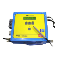
• Switch on heating element and set the required welding temperature on the rotary type
regulator. If the control light flashes, the nominal temperature has been reached and is held
at a constant level (Chapter4.3).
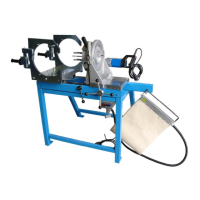
• Set the desired angle at the clamping tools.
• The left clamping tool can be moved forwards and backwards.
• The angle settings 11,25° and 15° can be read at the figure stamps.
• Screw the clambing tools according to the pipe outside diameter to be welded
• Lay the work pieces into the clamping shells, fasten the clamping screws and align the work
pieces to each other.
• Use the WIDOS rollerstand for the alignment of long pipe ends, for bows use the
supporting angle and pipe supports.
• Close the machine meanwhile reading the travel pressure at the manometer.
• The travel pressure is displayed exactly at that moment when the machine with the
clamped pipe starts moving.
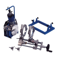
• Then open the machine again in such a way that the planer fits in between.
• Swivel in the planer between the ends of the workpieces and let the planer lock.
• Switch on the planer, close the machine and plane with a pressure that lies between 1 and
15 bar over the travel pressure.
• If necessary, use the plane girder for planing only at one side (if planing to size or if using a
welding neck which means that only a little material may be removed).
• Planing should be carried out until a revolving cutting has been formed on both sides.
• Open the machine again, switch off the planer and swivel back the planer out of the
machine.
• Remove the formed chips without touching the surfaces.
• Close the machine.