Kunststoffschweißtechnik
Starting and operating Chapter 5
25.06.12 Working instructions WIDOS 4001 Page 23 of 59
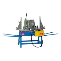
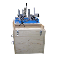
5.2.1. Plane girder for planing only at one side
If planing is necessary only at one side (e.g. at
use of a fitting) the plane girder for planing (A) is
used.
Center the centering bolt of the girder in the
central drill.
Of the planer and hold tightly the girder during
planing.
5.3. Welding logs and tables
If welding angles, the welding surface of the pipe and thus the necessary pressure changes.
Calculate the necessary pressure as follows:
• Take the prescribed value for adjusting or cooling from the table.
• Multiplicate the pressure value with factor /cos (angle).
This will give the following factors:
Welding 15° (chamfered pipe with 7,5°): 1,01
Welding 22,5° (chamfered pipe with 11,25°): 1,02
Welding 30° (chamfered pipe with 15°): 1,04
Welding 45° (chamfered pipe with 22,5°): 1,08
Welding 60° (chamfered pipe with 30°): 1,15
Welding 90° (chamfered pipe with 45°): 1,41
• Add the motional pressure as usual.
All the other welding parameters remain as usual.
5.4. Welding segmented bends
Calculate the sawing angle to be set (corresponding to the required angle at the clamping
tools or clamping inserts) as follows:
angle of the bend
sawing angle = ---------------------------------------------
number of all welding surfaces
Example 1: bend of 90° 4 segments (6 welding surfaces)
90°
sawing angle = ----- = 15°
6
Example 2: bend of 45° in 3 segments (4 welding surfaces)
45°
sawing angle = ----- = 11,25°
4
angle