SA-IN Input Module
© 2010 Wieland Electric GmbH | BA000256 | 12/2012 (Rev. I)
35
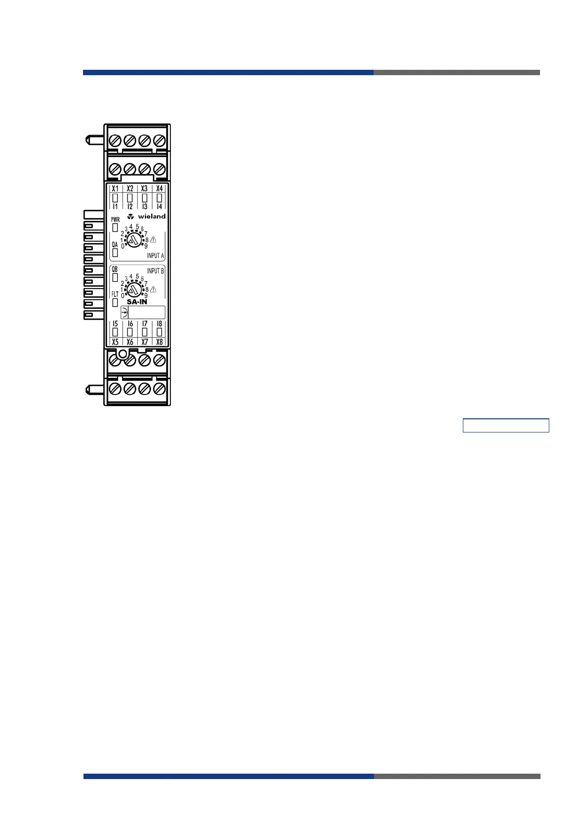
Interfaces and Operation
Clamps
I1, I2, I3, I4 Inputs for connection of signal transmitters /
sensors (functional group A)
X1, X2, X3, X4 Outputs only for input circuit voltage or
rather control sensors of the module
(functional group A)
I5, I6, I7, I8
Inputs for connection of signal transmitters /
sensors (functional group B)
X5, X6, X7, X8 Outputs just for the input circuit voltage or
rather control sensors of the module
(functional group B)
SBus 10-pin connector for safety bus (plug and
nut)
Push-buttons
INPUT A
INPUT B
10-staged torque switch for adjustment of an
input circuit function (functional group A or
rather B)
LEDs
I1.. I8 (green)
PWR (green)
QA (green)
QB (green)
FLT (red)
Indicators of according inputs
Voltage supply
Overall indicator of inputs I1..I4 (functional
group A)
Overall indicator of inputs I5..I8 (functional
group )
Indicator of flawed operating modes
(see FLT error codes page 63)
___________________________________________________________________________
PWR on
I1-I8 on
I1, I2 flash simultaneously
I3, I4 flash simultaneously
I5, I6 flash simultaneously
I7, I8 flash simultaneously
I1, I2 flash alternately
I3, I4 flash alternately
I5, I6 flash alternately
I7, I8 flash alternately
I1 or I2 flashes
I3 or I4 flashes
I5 or I6 flashes
I7 or I8 flashes
QA on
QB on
FLT off
Power supply to module electronics is on
H-level on corresponding input
Cross-circuit between I1 and I2
Cross-circuit between I3 and I4
Cross-circuit between I5 and I6
Cross-circuit between I7 and I8
Sequence error on I1, I2
Sequence error on I3, I4
Sequence error on I5, I6
Sequence error on I7, I8
Synchronous time error. The input that flashes is the one
that achieves good state too late.
Synchronous time error. The input that flashes is the one
that achieves good state too late.
Synchronous time error. The input that flashes is the one
that achieves good state too late.
Synchronous time error. The input that flashes is the one
that achieves good state too late.
Good state of AND-linked input pairs I1/I2 and I3/I4
(function group A)
Good state of AND-linked input pairs I5/I6 and I7/I8
(function group B)
No fault states
Meaning of LEDs
 Loading...