SA-IN Input Module
32
© 2010 Wieland Electric GmbH | BA000256 | 12/2012 (Rev. I)
5 SA-IN Input Module
Input Module Data
SA-IN-S1,
Input Module
The input module adds additional input circuits or logic
functions to a base module on its left (SA-BM master).
ou can operate several input modules on one base
module.
There are two function groups, A and B, each with
four inputs and four sensor supplies. You can set one of
10 functions for each group independently, using the
rotary switches on the front. The configuration will be
permanently saved in the master base module. The
device operates as a slave on the internal safety bus.
SA-IN-S1
SA-IN
The controller category (EN ISO 13849-1) or SIL (EN 61508/EN 62061) depends on the
external circuitry, the wiring, the choice of control devices and their location on the
machine.
The rotary switches for selecting function must only be adjusted when power is off.
Never connect or disconnect modules while the operating voltage is switched on.
Internal samos module addresses are assigned automatically when the system starts up.
Manual addressing is unnecessary (and not possible).
The safety system must be installed in an enclosure with at least IP 54 protection.
Input modules are always assigned functionally to the next connected base module to
the left. Each base module forms a system group within the overall system (sometimes
together with associated input expansion modules; see diagram on page 8).
Base modules and input modules are uniquely coded depending on their system system
group (see diagram on page 8).
Accepting the system configuration
For accepting the system configuration see page 18.
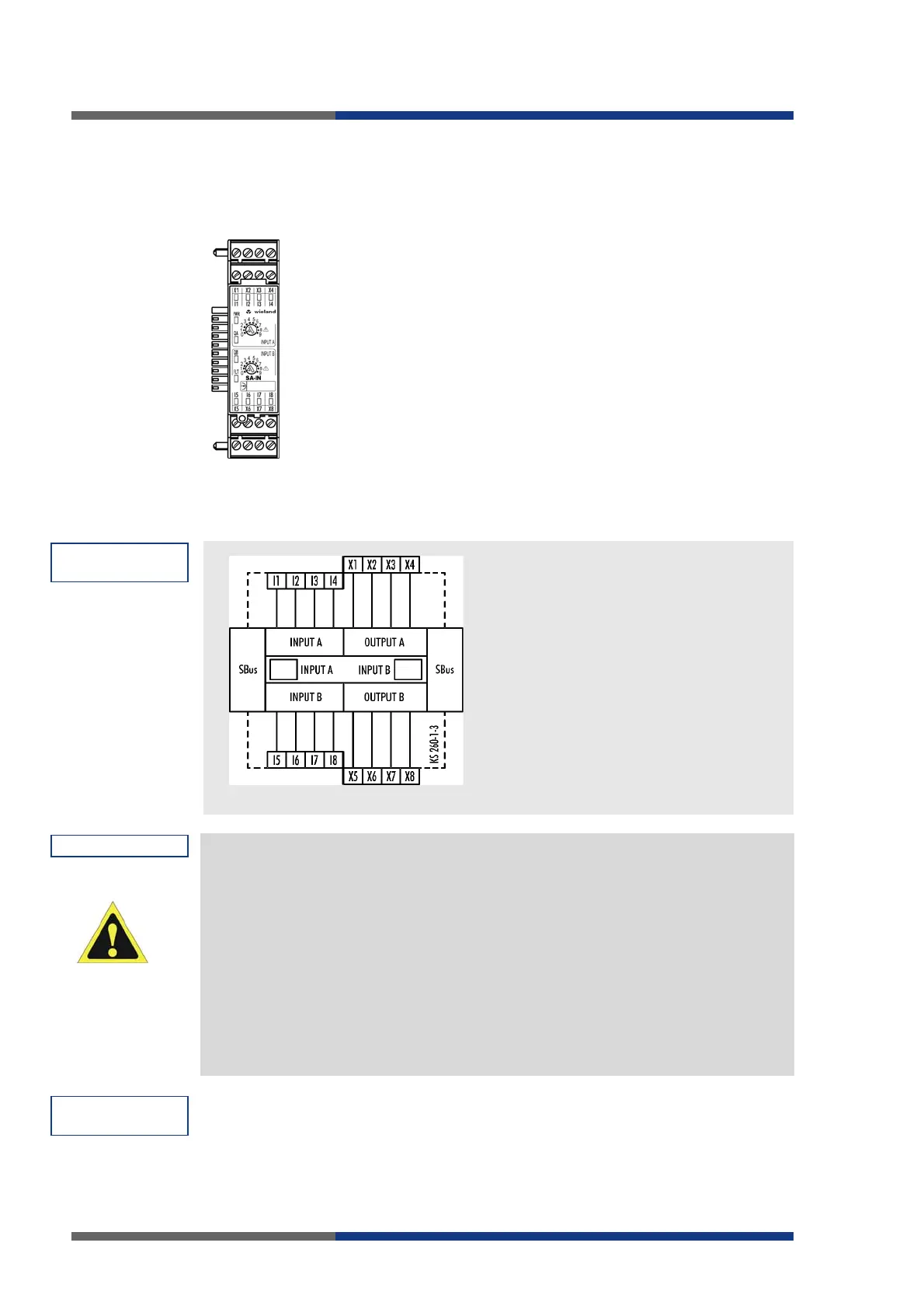
Connection
diagram
Notes
Accepting
configuration
 Loading...