SA-OR-S1 / SA-OR-S2 Relay Output Modules
44
© 2010 Wieland Electric GmbH | BA000256 | 12/2012 (Rev. I)
Interfaces and Operation
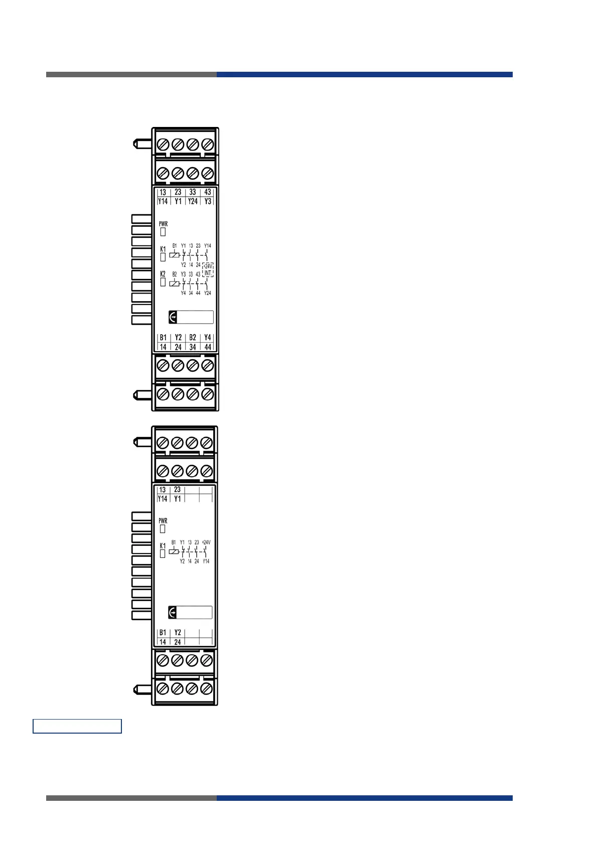
SA-OR-S1
Clamps
B1 Input relay K1
13/14, 23/24 Floating output circuits K1
14
Single-ended output circuit K1
B2 Feedback circuit K1
1/Y2 Input relay K2
33/34, 43/44 Floating output circuits K2
24 Single-ended output circuit K2
3/Y4 Feedback circuit K2
SBus 10-pin connector for safety bus (plug and
nut)
LEDs
PWR (green)
K1 (green)
K2 (green)
Voltage supply
Relay K1
Relay K2
SA-OR-S2
Clamps
B1 Input relay K1
13/14, 23/24 Floating output circuits K1
14
Single-ended output circuit K1
1/Y2 Feedback circuit K1
SBus 10-pin connector for safety bus (plug and
nut)
LEDs
PWR (green)
K1 (green)
Voltage supply
Relay K1
____________________________________________________________________
PWR on
K1 on
K2 on
Power supply to module electronics is on
Relay K1 in operated condition
Relay K2 in operated condition
Meaning of LEDs
 Loading...