SA-IN Input Module
© 2010 Wieland Electric GmbH | BA000256 | 12/2012 (Rev. I)
41
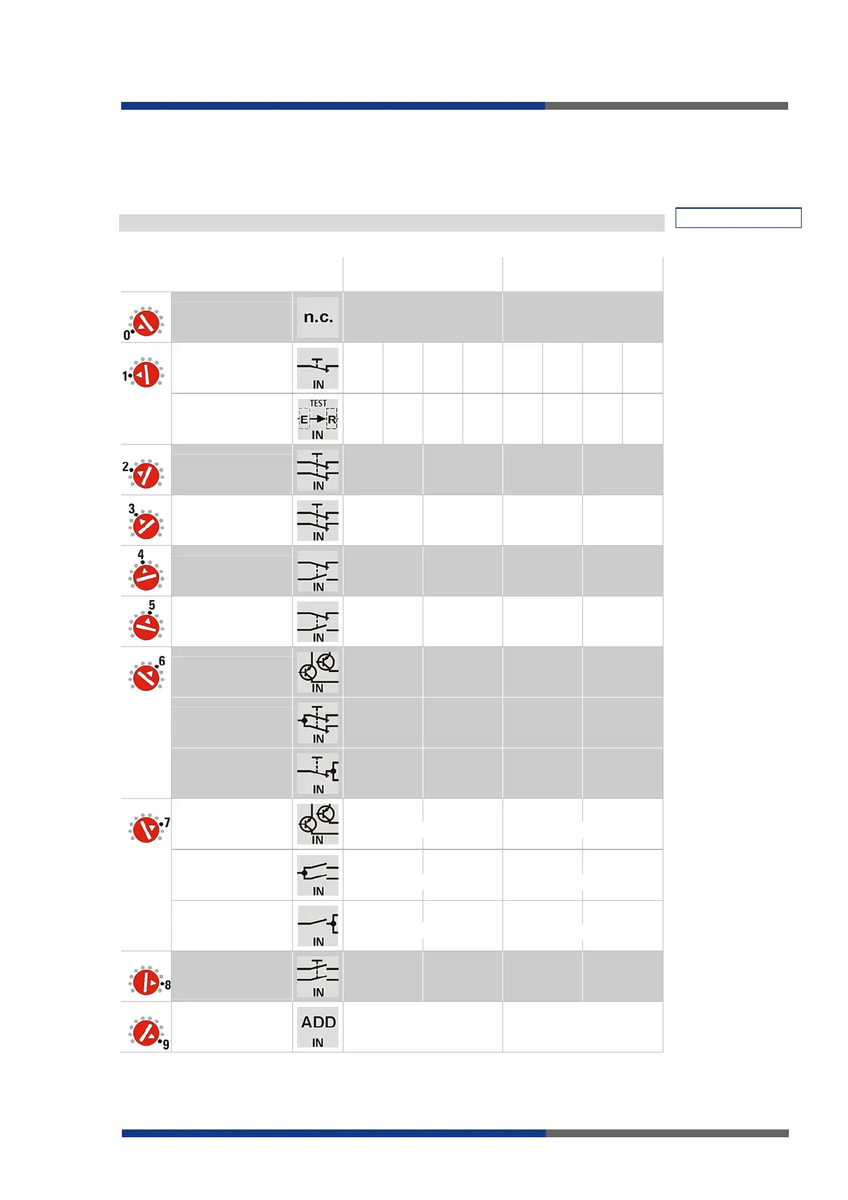
Terminal Assignment
The assignment of outputs X1 to X8 to inputs I1 to I8 depends on the selected input circuit
function. The functions of groups A and B can be set independently.
Unused inputs must be bridged according to the illustrated good state.
INPUT A / INPUT B
Input terminal pairs
function group A
Input terminal pairs
function group B
All inputs of group
A / group B unused
n.c. terminals n.c. terminals
4x single-channel
with testing
X1-I1 X2-I2 X3-I3 X4-I4 X5-I5 X6-I6 X7-I7 X8-I8
4x single-channel
with testable
sensors*
X1-I1 X2-I2 X3-I3 X4-I4 X5-I5 X6-I6 X7-I7
X8-I8
2x dual-channel
Cross monitoring
X1-I1
X2-I2
X3-I3
X4-I4
X5-I5
X6-I6
X7-I7
X8-I8
2x dual-channel
Cross monitoring
Synchro-check
X1-I1
X2-I2
X3-I3
X4-I4
X5-I5
X6-I6
X7-I7
X8-I8
2x dual-channel
Cross monitoring
X1-I1
X2-I2
X3-I3
X4-I4
X5-I5
X6-I6
X7-I7
X8-I8
2x dual-channel
Cross monitoring
Synchro-check
X1-I1
X2-I2
X3-I3
X4-I4
X5-I5
X6-I6
X7-I7
X8-I8
2x dual-channel
Semiconductor
Q1
Sensor
-I1
Q2
Sensor
-I2
Q1
Sensor
-I3
Q2
Sensor
-I4
Q1
Sensor
-I5
Q2
Sensor
-I6
Q1
Sensor
-I7
Q2
Sensor
-I8
2x dual-channel
Three-wire
U
X
-I1
U
X
-I2
U
X
-I3
U
X
-I4
U
X
-I5
U
X
-I6
U
X
-I7
U
X
-I8
2x single-channel
U
X
-I1
U
X
-I2
U
X
-I3
U
X
-I4
U
X
-I5
U
X
-I6
U
X
-I7
U
X
-I8
OR
2x dual-channel
semiconductor
Q1
Sensor
-I1
Q2
Sensor
-I2
Q1
Sensor
-I3
Q2
Sensor
-I4
Q1
Sensor
-I5
Q2
Sensor
-I6
Q1
Sensor
-I7
Q2
Sensor
-I8
OR / MUTING
2x dual-channel
Three-wire
U
X
-I1
U
X
-I2
U
X
-I3
U
X
-I4
U
X
-I5
U
X
-I6
U
X
-I7
U
X
-I8
OR
2x single-channel
U
X
-I1
U
X
-I2
U
X
-I3
U
X
-I4
U
X
-I5
U
X
-I6
U
X
-I7
U
X
-I8
BYPASS
1x dual-channel
Cross monitoring
X1-I1
X2-I2
I3 n.c.
I4 n.c.
X5-I5
X6-I6
I7 n.c.
I8 n.c.
Input expansion
Function as INPUT B Function as INPUT A
NOTE
* Non-contact safety
device type 2.
For the U
X
voltage see
page 22.
1
1
1 1
1
1
 Loading...