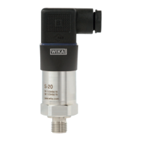
41WIKA Betriebsanleitung Druckmessumformer, Typ S-20
D
14043170.01 04/2013 GB/D/F/E
6. Inbetriebnahme, Betrieb
Die zulässige Hilfsenergie ist vom jeweiligen Ausgangssignal abhängig.
Bei cULus-Zulassung: max. DC 35 V (DC 32 V bei Heavy-Duty-Connector)
Ausgangssignal Hilfsenergie
4 ... 20 mA DC 8 ... 36 V (DC 12 ... 36 V bei optionaler Einschwingzeit 1 ms)
20 ... 4 mA DC 8 ... 36 V
DC 0 ... 10 V DC 12 ... 36 V
DC 0 ... 5 V DC 8 ... 36 V
DC 1 ... 5 V DC 8 ... 36 V
DC 0,5 ... 4,5 V DC 8 ... 36 V
DC 1 ... 6 V DC 9 ... 36 V
DC 10 ... 0 V DC 12 ... 36 V
DC 0,5 ... 4,5 V DC 5 V ±10 %
Ausgangssignal Bürde in Ω
Stromausgang ≤ (Hilfsenergie - 7,5 V) / 0,023 A
≤ (Hilfsenergie - 11,5 V) / 0,023 A (bei optionaler Einschwingzeit 1 ms)
Spannungsausgang > maximale Ausgangsspannung / 1 mA
Ratiometrischer Ausgang > 4,5 kΩ
Verlustleistung
■
Stromausgang: 828 mW (22 mW/K Derating der Verlustleistung bei Umgebungstemperaturen ≥ 100 °C)
■
Spannungsausgang: 432 mW
Stromaufnahme
■
Stromausgang: Stromsignal, max. 25 mA
■
Spannungsausgang: max. 12 mA
 Loading...