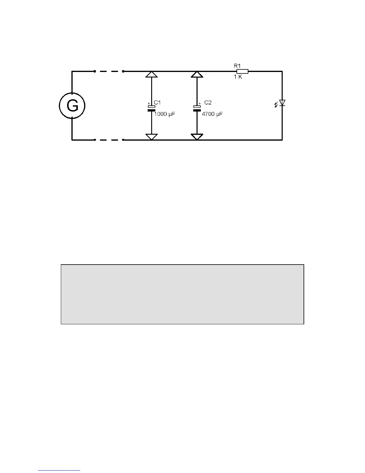
Fig.3.39: circuit diagram, both electrolytic are marked in with an arrow to
show that they are used alternatively
The light of the LED goes out shortly and then starts to flash a little less
bright after plugging in the electrolytic 1000µF. Now you replace the
electrolytic 1000µF with the 4700µF in the next step and a calm light will
shine. If you would measure with an oscilloscope the smoothed voltage you
would almost see no wave at all on the diagram.
Picturing the electronically smoothing process:
To create a picture for the expression “smoothing electricity through an
electrolytic” we imagine that electricity behaves like water. We can
compare an electrolytic with “a water bucket with a hole in the bottom”
If you fill intermittently the bucket with a ladle with water, it would
continuously flow out of the hole in an uninterrupted stream.
3.7.1 More light with 2 white LEDs
Assembly of the experiment: components like before, add one white LED
and plug it parallel next to the first one. Both LEDs are connected with the
series resistor 1 K-Ohm (brown, black, red, gold).