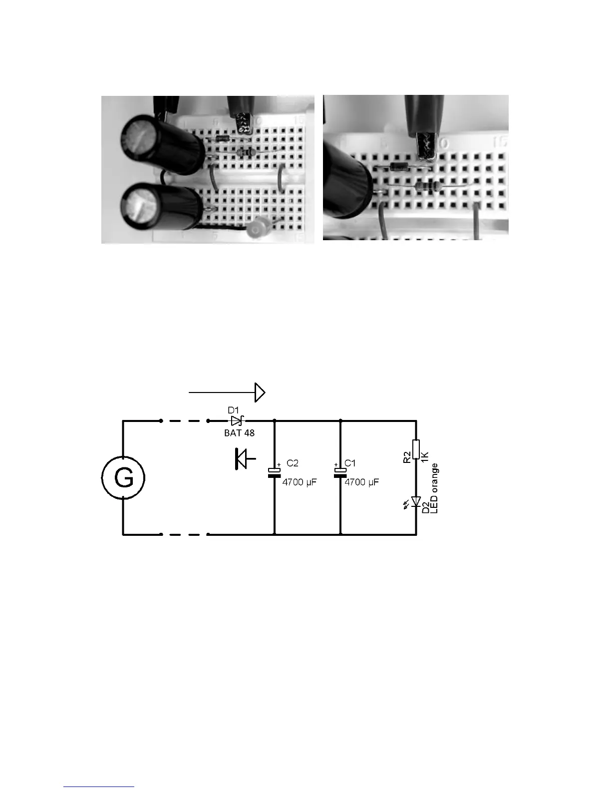
Fig.3.49: Assembly of the experiment, b) detail: mounting of the diode, the
black ring (cathode) is on the left side of the picture
This experiment shows that the electrolytic is charged by the generator, is
keeping the voltage and storing it.
Fig.3.50: circuit diagram: discharge protection diode
You can measure the voltage which is stored in the electrolytic with a
multimeter. Switch the multimeter onto the direct current measuring area
(DC,20V).and connect the cables of the multimeter with the connection
wires of the electrolytic according to the polarity.