TEST/DIAGNOSTIC PROCEDURES (Continued)
SOLENOID TEST.
1.
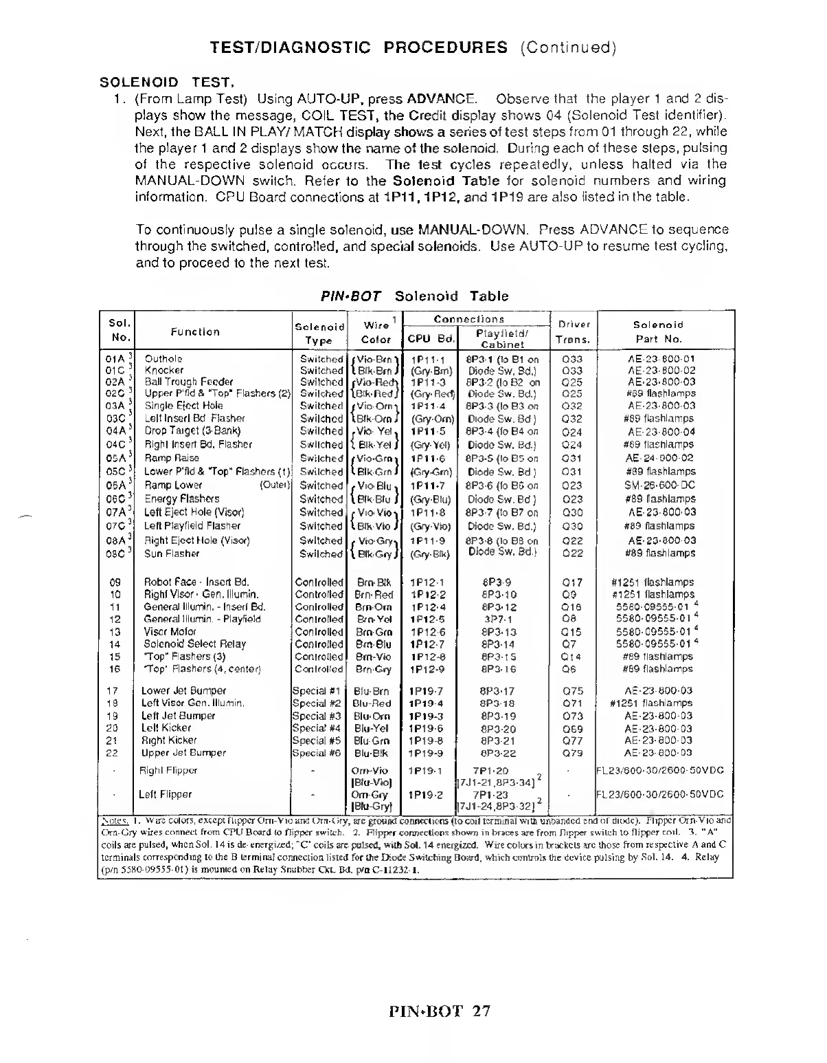
(From Lamp Test) Using AUTO-UP, press ADVANCE. Observe that
the player 1 and 2 dis-
plays show the message, COIL TEST, the Credit display shows
04
(Solenoid Test
identifier).
Next, the BALL
IN PLAY/
MATCH display shows
a
series of
test
steps
from
01
through
22,
while
the
player
1
and
2 displays show the name of the solenoid.
During each of these
steps,
pulsing
of the respective
solenoid
occurs.
The test
cycles repeatedly, unless halted via the
MANUAL-DOWN switch. Refer
to
the Solenoid Table for solenoid numbers and
wiring
information. CPU Board
connections
at
1 P1
1 ,
1P12,
and
1 PI 9
are also listed in the table.
To continuously
pulse a
single solenoid,
use MANUAL-DOWN.
Press ADVANCE to sequence
through the switched, controlled,
and
special
solenoids. Use
AUTO-UP
to
resume test cycling,
and
to
proceed
to the
next
test.
PIN-BOT Solenoid Table
Sol.
Solenoid
Type
Wire
1
Color
Connections
Driver
Trans.
Solenoid
Part No.
No.
Function
CPU Bd.
Playfield/
Cabinet
01 A
3
Oulhole
Switched rVio-Brnl 1P11-1 8P3-1 (to
B1 on
033 AE-23-800
01
01 c
3
02A
3
Knocker
Switched
l
Blk-Brn
/
(Gry-Bm)
Diode Sw. Bd.)
033 AE-23-800-02
Ball Trough Feeder
Switched rVio-Redy 1
P1
1-3
8P3-2 (to B2 on 025 AE-23-800-03
02C
3
03A
3
03C
04
A
3
04C
3
05A
3
Upper P'fld & Top”
Flashers
(2)
Switched TBIk-RedJ (Gry-Red) Diode Sw.
Bd.)
025
#89 flashlamps
Single Eject Hole
Switched rVio-Orni 1 P1
1-4
8P3-3 (to B3 on Q32
AE-23-800-03
Left Inserl Bd Flasher
Switched l Blk-Orn I (Gry-Orn) Diode Sw. Bd.) 032 #89
flashlamps
Drop Target (3-Bank)
Switched
;
Vio- Yel, 1 P1
1-5
8P3-4 (to B4 on
024
AE-23-800-04
Right Inserl Bd. Flasher Switched
i
Blk-Yel
/
(Gry-Yel) Diode Sw. Bd.)
Q24 #89 flashlamps
Ramp Raise
Switched rVio-Grni
1P11-6 8P3-5
(to B5
on
031 AE-24-900-02
05C
3
06A
3
Lower P'fld & "Top' Flashers
(1)
Switched 1
Blk-Grn
/
(Gry-Gm) Diode Sw. Bd.)
Q31 #89 flashlamps
Ramp Lower
(Outer;
Switched t Vio-Blu
•»
1P11-7
6P3-6 (to
B6
on Q23
SM-26-600-DC
06C
3
Energy Flashers
Switched
1
Blk-Blu
/
(Gry-Blu) Diode Sw. Bd.) 023
#89 flashlamps
07A
3
Lett
Eject Hole
(Visor) Switched r VlO-ViOl
1 P 1
1-8
8P3-7 (to
B7 on
Q30 AE-23-800-03
07C
3
,
Lett Playfield Flasher
Switched 1
Blk-Vio
/ (Gry-Vio) Diode Sw. Bd.) 030
#89 flashlamps
08A
3
Right Eject Hole (Visor)
Switched , Vio-Gry-,
\
Blk-Gry
J
1 P1
1-9
8P3-8 (to B8 on Q22 AE-23-800-03
08C
3
Sun Flasher
Switched (Gry-BIk)
Diode Sw. Bd.)
Q22
#89 flashlamps
09
Robot Face
-
Insert Bd
Controlled Brn-Blk 1P12-1 8P3-9 Q17 #1251
flashlamps
10 Right Visor
•
Gen. Illumin. Controlled
Brn-Red
1P12-2 8P3-10
09
#1251 flashlamps
11 General
Illumin.
-
Insert Bd Controlled
Brn-Orn
1P12-4 8P3-12 Q16
5580-09555-01
4
12
General Illumin
-
Playfield
Controlled Brn-Ycl 1P12-5 3P7-1
08
5580-09555-01
4
13
Visor Molor
Controlled Brn-Grn 1 PI
2-6
8P3-13 015
5580-09555-01
4
14 Solenoid Select Relay
Controlled Brn-Blu 1P12-7 8P3-14 07
5580-09555-01
4
15
•Top" Flashers
(3)
Controlled
Brn-Vio 1 PI
2-8
8P3-15 Q14
#89 flashlamps
16 Top'
Flashers
(4,
center) Controlled Brn-Gry
1P12-9
8P3-16
Q6
#89
flashlamps
17 Lower Jet Bumper Special #1
Blu-Brn I
P19-7
8P3-17 075
AE-23-800-03
18
Left Visor Gen Illumin.
Special #2 Blu-Red 1P19-4 8P3-18 071 #1251
flashlamps
19 Left
Jet Bumper
Special #3 Blu-Om 1P19-3 8P3-19 073 AE-23-800-03
20 Left Kicker Special #4
Blu-Yel 1P19-6
8P3-20 069 AE-23-800-03
21 Right Kicker
Special #5 Blu-Grn 1 Pi
9-8
8P3-21 077
AE-23-800-03
22
Upper Jet Bumper
Special #6 Blu-BIk
1 PI
9-9
8P3-22
079 AE-23-800-03
-
Right Flipper
-
Orn-Vio
IBIu-Vio)
1P19-1 7P1-20
|7J1-21
.8P3-34
)
1
FL23/600-30/2600-50VDC
Lell
Flipper
Orn-Gry
(Blu-Gry)
1P19-2 7P1-23
7J1-24.8P3-32)
FL
23/600-30/2600- 50VDC
Nines: 1 . Wire colors, except (Upper Oni-Vio
and Orn-Gry, arc ground connections (to coil terminal with unhanded
end of diode). Flipper Orn-Vio and
Orn-Gry
wires
connect from
CPU Board to flipper switch. 2. Flipper
connections
shown in braces are
from flipper
switch
to
flipper
coil.
3. "A"
coils are
pulsed, when
Sol.
14 is de-energized;
"C
coils are pulsed,
with
Sol. 14 energized. Wire colors in brackets are those
from respective
A
and
C
terminals
corresponding
to
the
B
terminal
connection listed
for
the Diode Switching Board, which controls
the
device pulsing
by
Sol.
14. 4. Relay
(p/n
55X0-09555-01) is
mounted on
Relay Snubber Ckt Bd.
p/n C- 11
232-1.
PIN*BOT
27
 Loading...