TEST/DIAGNOSTIC
PROCEDURES
(Continued)
SOLENOID
TEST (Continued)
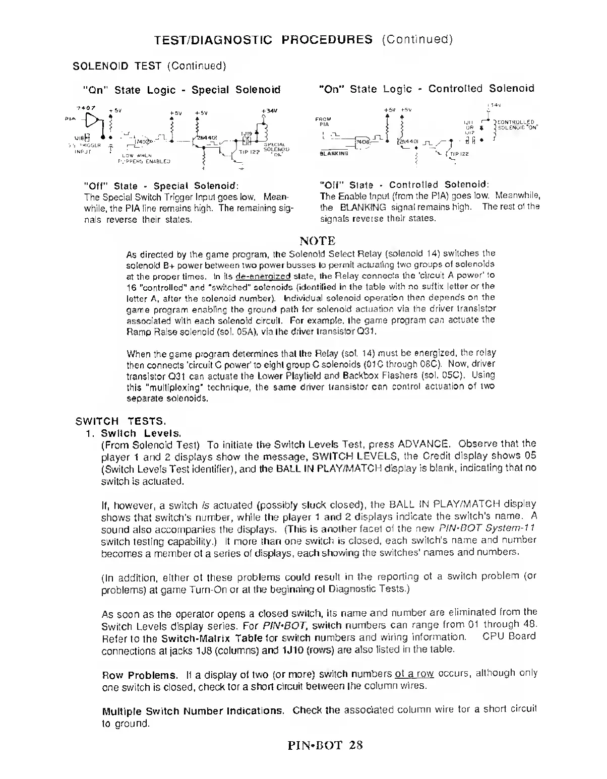
"On”
State Logic
-
Special
Solenoid "On”
State Logic
-
Controlled Solenoid
"Off" State
-
Special Solenoid:
The Special Switch
Trigger Input goes low.
Mean-
while, the PIA line
remains high. The
remaining sig-
nals reverse their states.
"Off” State
-
Controlled
Solenoid:
The
Enable Input (from the
PIA) goes low.
Meanwhile,
the BLANKING signal remains
high. The rest
of the
signals reverse
their states.
NOTE
As
directed
by
the game
program, the Solenoid Select
Relay (solenoid
14)
switches the
solenoid B+
power between two power busses to
permit actuating
two groups of
solenoids
at the
proper times. In its
de-eneroized slate, the Relay
connects the 'circuit A
power' to
16
"controlled" and "switched" solenoids
(identified in the table
with no suffix
letter or the
letter A, after the solenoid number).
Individual solenoid
operation then
depends on the
game program enabling the ground
path for solenoid
actuation via the
driver
transistor
associated with each solenoid circuit.
For example, the
game program
can actuate the
Ramp Raise
solenoid (sol. 05A), via the driver
transistor Q31.
When the game
program determines that the
Relay (sol.
14)
must be energized,
the relay
then connects
'circuit C power' to eight
group C solenoids (01 C
through 08C). Now,
driver
transistor Q31 can actuate
the Lower Playfield
and Backbox Flashers
(sol. 05C).
Using
this "multiplexing"
technique, the same driver
transistor can
control actuation
of two
separate solenoids.
SWITCH TESTS.
1. Switch Levels.
(From Solenoid Test) To initiate
the Switch Levels Test,
press ADVANCE.
Observe that
the
player 1 and 2 displays show
the message, SWITCH
LEVELS, the
Credit display
shows
05
(Switch Levels Test identifier), and
the BALL IN
PLAY/MATCH display is
blank, indicating
that no
switch is actuated.
If,
however,
a
switch is actuated
(possibly stuck closed),
the BALL
IN
PLAY/MATCH display
shows that switch's number,
while the player 1 and 2
displays
indicate the
switch’s name. A
sound also
accompanies the displays. (This is
another facet
of the new
PIN‘BOT System-1
1
switch testing
capability.) If more than one
switch is closed,
each switch's
name and
number
becomes a
member of
a
series of displays,
each showing
the switches'
names and
numbers.
(In addition,
either of these
problems could result
in the reporting
of a switch
problem
(or
problems) at
game Turn-On or at
the beginning of
Diagnostic Tests.)
As soon
as
the
operator opens
a
closed
switch, its name
and
number are
eliminated
from the
Switch Levels display series.
For PIN-BOT,
switch
numbers can
range from
01 through
48.
Refer to the
Switch-Matrix
Table for switch
numbers and
wiring
information.
CPU Board
connections at jacks
1
J8
(columns)
and 1
J
10 (rows) are
also listed
in the
table.
Row Problems.
It
a
display of
two (or more) switch
numbers
of
a
row occurs,
although
only
one switch is closed,
check for
a
short
circuit between the
column
wires.
Multiple
Switch Number
Indications. Check
the associated
column
wire for a
short circuit
to
ground.
PIN»BOT
28