TEST/DIAGNOSTIC
PROCEDURES (Continued)
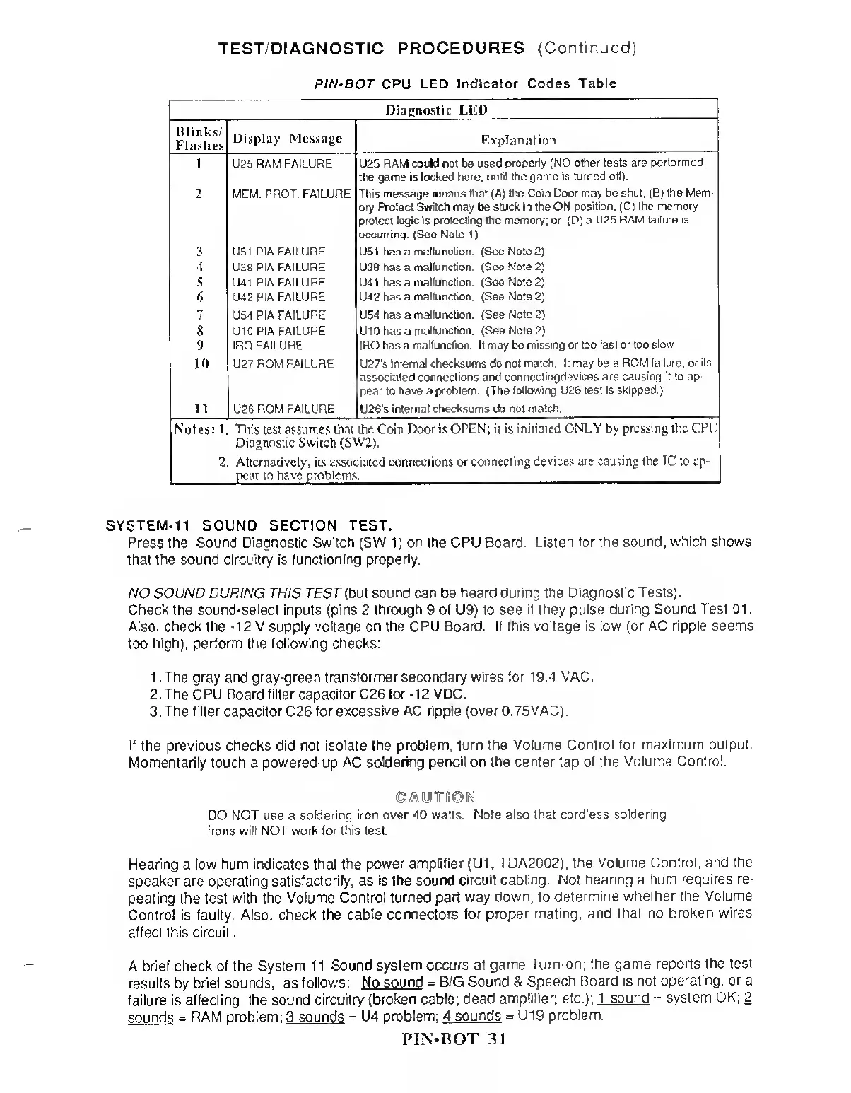
PIN'BOT CPU LED
Indicator Codes
Table
Diagnostic LED
Blinks/
Flashes
Display Message
Explanation
U25
RAM FAILURE U25 RAM could
not
be used
properly (NO other tests
are performed:
the game is
locked here,
until the
game is
turned off).
MEM.
PROT. FAILURE This message moans that (A) the
Coin Door may be shut, (B) the Mem-
ory Protect
Switch
may be stuck in the
ON position, (C) the memory
protect logic is
protecting
the
memory; or
(D) a
U25 RAM failure is
occurring.
(See
Note
1)
U51 P1A
FAILURE
U51 has a
malfunction. (See Note
2)
U38 PIA FAILURE U38 has a
mallunction. (See Note
2)
U41 PIA FAILURE U41
has
a
malfunction (Seo Note
2)
U42 PIA FAILURE U42
has a
malfunction.
(See Note
2)
U54 PIA
FAILURE U54 has a
malfunction.
(See
Note
2)
8
U10PIA FAILURE U10 has a
malfunction. (See Note
2)
WlM
IRQ FAILURE IRQ has a malfunction. It may
be missing or too fast or too
slow
U27
ROM FAILURE U27's
internal
checksums do not
match. It may be a ROM
failure, or its
associated connections and
connectingdevices are causing it to ap-
pear to have a problem. (The
following U26 test is skipped.)
mM
U26 ROM FAILURE U26‘s
internal checksums do not match.
Notes: 1 Tins
test
assumes that the Com Door is
OPEN; it is initiated ONLY by
pressing the CPU
Diagnostic Switch
(SW2).
2. Alternatively, its associated connections or
connecting devices are causing the
TC
to ap-
pear to have problems.
SYSTEM-11 SOUND SECTION TEST.
Press the Sound Diagnostic Switch (SW
1)
on the CPU
Board. Listen tor the
sound, which shows
that the sound circuitry is
functioning properly.
NO SOUND DURING THIS TEST (but sound can
be
heard during the
Diagnostic Tests).
Check the sound-select inputs (pins 2 through 9 ol U9) to see
if they pulse during
Sound Test 01.
Also, check the
-12
V supply voltage on the CPU Board. If this voltage is
low (or AC ripple seems
too
high), perform the following checks:
1 . The gray and gray-green transformer secondary wires for 1
9.4 VAC.
2. The CPU Board filter capacitor C26 for
-12
VDC.
3.
The filter capacitor
C26
for excessive AC ripple (over 0.75VAC).
If the previous checks did not
isolate the problem, turn the Volume
Control for maximum output.
Momentarily touch a
powered-up AC soldering pencil on the center tap
of the Volume Control.
CAUTIOK
DO NOT use a
soldering iron over 40 watts. Note also
that cordless soldering
irons will NOT work for this test.
Hearing
a
low hum indicates that the power
amplifier
(U1
,
TDA20Q2),
the Volume Control, and
the
speaker are operating satisfactorily, as is
the sound circuit cabling.
Not hearing a
hum requires re-
peating the test
with
the
Volume Control
turned part way down, to
determine
whether the Volume
Control is
faulty.
Also,
check the cable
connectors for
proper mating, and that
no broken wires
affect this circuit
.
A brief check
of the
System
1
1
Sound system occurs at
game
Turn-on; the
game reports the test
results
by
brief
sounds,
as
follows: No
sound =
B/G
Sound &
Speech
Board is not operating,
or
a
failure is affecting
the sound circuitry (broken cable; dead
amplifier;
etc.);
1 sound = system
OK; 2
sounds
= RAM
problem:
3
sounds =
U4
problem: 4 sounds
=
U19
problem.
PIN-BOT 31