en
12 Installation and operating instructions • Wilo-Control SC2.0-Booster • Ed.01/2023-09
The previous base-load pump continues to run at max. speed as a peak-load pump. This
procedure is repeated at increasing load until the maximum number of pumps is reached
(here: 3 pumps).
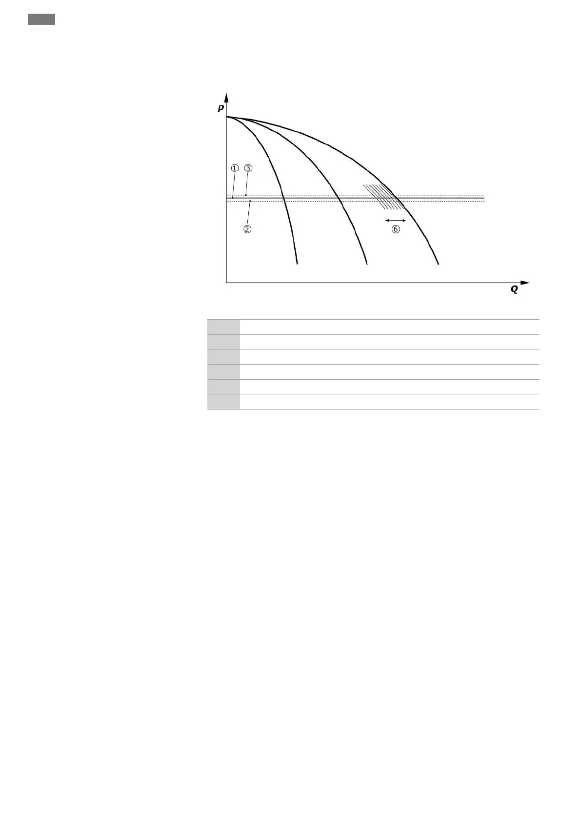
Fig.7: Starting the third pump
1 Reference setpoint of system pressure
2 Activation threshold of the base-load pump
3 Deactivation threshold of the base-load pump
4 Activation threshold of the peak-load pumps
5 Deactivation threshold of the peak-load pumps
6 Speed setpoint of the base-load pump
If the requirement decreases, the controlling pump is switched off when the set speed is
reached and the reference setpoint is exceeded at the same time. A peak-load pump that
was previously acting takes over the control.
• Set speed: System→Frequency converter→Limits
If no peak-load pump is active anymore, the base-load pump switches off when the deac-
tivation threshold (3) is exceeded and after the delay time has elapsed, if necessary, after a
zero-flow test.
• Set the deactivation threshold: Control setting→Setpoints→Switching on and off of BLP
• Set the delay time: Control setting→Setpoints→Delays
Delay times can be set for activation and deactivation of the peak-load pump.
• Set the delay times: Control setting→Setpoints→Delays
Control mode p-c, cascade mode
In the base-load pump mode “cascade”, the base-load pump is not changed when the
peak-load pump is switched on or off and only the speed is adjusted accordingly.
• Set mode: Control settings→Control→BLP selection diagram
p-v control mode
An electronic pressure transmitter supplies the actual pressure value as a 4…20mA or
0…20mA current signal. Then the control device maintains the system pressure at a con-
stant level by means of the comparison of the setpoint/actual value.
• Set measurement range: System→Sensors→Discharge side measurement range
• Set sensor type: System→Sensors→Discharge side sensor type
The setpoint is dependent on the current volume flow and is between the setpoint at zero
flow (2) and the reference setpoint (1) when the volume flow of the unit is at a maximum
(without standby pump) (3).
• Control settings→Setpoints→Setpoints 1