en
Installation and operating instructions • Wilo-Control SC2.0-Booster • Ed.01/2023-09 39
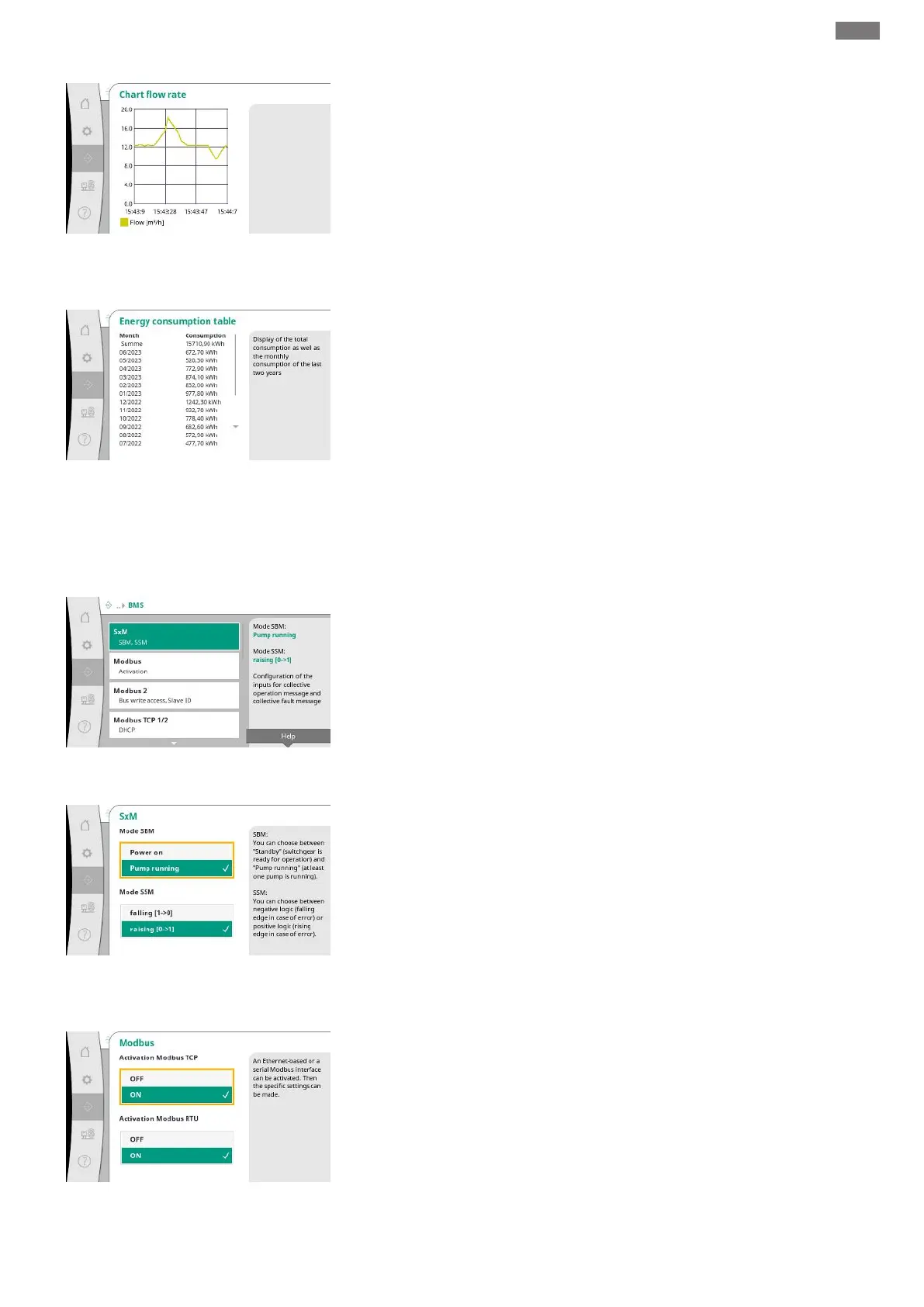
Fig.69: Communication→Diagnosis and
measured values→Flow rate chart menu item
History of the estimated flow rate in the past minutes.
Fig.70: Communication→Diagnosis and
measured values→Energy consumption table
menu item
Displays the estimated total power consumption as well as the monthly consumption of the
last two years.
7.2.2.3 Interaction / Communication ->
BMS menu
Fig.71: Communication→BMS menu item
Menu for the interfaces to the building management system.
Fig.72: Communication→BMS→SxM menu
item
For “SBM”, you can choose between “Standby” (control device is ready for operation) and
“Pump running” (at least one pump is running).
For “SSM”, you can choose between negative logic (falling edge in case of error) or positive
logic (rising edge in case of fault).
Fig.73: Communication→BMS→Modbus
menu item
An Ethernet-based or a serial Modbus interface can be activated.
Specific settings of the interface can be made.