en
40 Installation and operating instructions • Wilo-Control SC2.0-Booster • Ed.01/2023-09
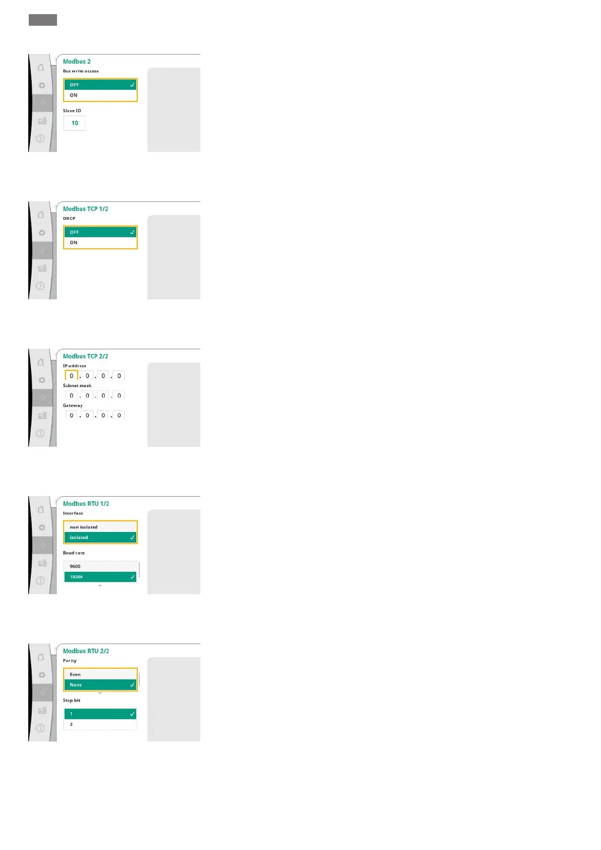
Fig.74: Communication→BMS→Modbus 2
menu item
For Modbus, the “Slave ID” must be set.
Bus write access can be disabled.
If bus write access is disabled, the data points can only be read.
Fig.75: Communication→BMS→Mod-
bus TCP 1 menu item
If DHCP is activated, the network settings are requested from a DHCP server in the network
and not entered manually.
Fig.76: Communication→BMS→Modbus TCP
2 menu item
The IP address can only be configured via the WCP web pages.
Fig.77: Communication→BMS→Modbus RTU
1 menu item
“Interface”: “Isolated”, is intended for the Modbus RTU or BACnet MS/TP option.
“Not isolated” is the setting for Wilo internal use.
For Modbus RTU, the “baud rate” and the interfaces of the WCP can be selected.
The Modbus RTU option is required for the isolated interface.
Fig.78: Communication→BMS→Modbus RTU
2 menu item
The “parity” (“even”, “odd”, “none”) and the number of stop bits (1 or 2) can be set.