Installation and operating instructions Wilo-Drain TMT 32M 31
INSTALLATION English
Eitherapressurehoseoranexistingdischarge
pipeline is connected to the pressure side.
Ifthemotoremergesduringoperation,the
following operating parameters must be strictly
observed:
• The max. uid temperature and ambient tem-
perature is 75°C.
• Non-immersedoperatingmode:S325%
BEWARE of burns!
The housing parts can heat up to above
100°C. There is a risk of burns! After switch-
ing it off, let the pump cool down to ambient
temperature.
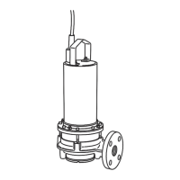
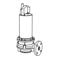
Discharge pipeline connection
NOTE
The pump is only held in place here by the pip-
ing. All vibrations and torques are transferred to
the pipe system!
Fig. 2.: Stationary installation
1 Pump 4 Impact protection plate
2 Discharge pipeline 5 Inlet
3 Non-return valve
6a
Min. water level for im-
mersed operation
6b
Min. water level for
non-immersed operation
Work steps
1. Preparingpumps:about1h
• Connectthepipeelbowtothepressureport
usingthethreadedange/angeconnection.
2. Installingthepump:about1-2h
• Oncethepipeelbowhasbeenconnected,posi-
tion the pump at the pressure pipe. If neces-
sary,secureliftingequipmenttothepumpwith
ashackle,liftthepumpandthenlowertothe
intendedlocation(sump,pit).
• Screw the pipe elbow onto the existing dis-
charge pipeline.
• Route the power supply cable in such a way
that it cannot be damaged.
• Have the electrical connections made by a
qualiedelectrician.
3. Commissioningthepump:about1-3h
• Asdescribedinthe“Commissioning”section
Connecting a pressure hose
RISK of pressure hose becoming separated!
Uncontrolled separation or movement of the
pressure hose can result in injuries. Secure the
pressure hose appropriately. Prevent buckling
of the pressure hose.
Work steps
1. Preparingpumps:about1h
• Fitthepipeelbowtothepressureconnection
using the hose connection.
• Fastenthepressurehosetothepipeelbow
with a hose clip.
2. Installingthepump:about1-2h
• Position pump in installation location. If neces-
sary,secureliftingequipmenttothepumpwith
ashackle,liftthepumpandthenlowertothe
intendedlocation(sump,pit).
• Checkthatthepumpisverticalandonasolid
bearing surface.
Avoid sinking.
• Route the power supply cable so it cannot be
damaged.
• Have the electrical connections made by a
qualiedelectrician.
• Route the pressure hose so that it is not
damaged and fasten it at certain points (e.g.
outow).
3. Commissioningthepump:about1-3h
• Asdescribedinthe“Commissioning”section
5.3.3. Level control
Filllevelscanbedeterminedusingthelevel
controlsystem,meaningthepumpisswitchedon
andoffautomatically.Thelllevelcanberecord-
edusingoatswitches,pressureandultrasound
measurements or electrodes.
Notethefollowinginformation:
• Whenusingoatswitches,ensurethattheycan
move freely in the operating area!
• The water level must not fall below the minimum!
• The maximum switching frequency may not be
exceeded!
• Ifthelllevelsuctuatestrongly,thenalevel
control should be made on two test points as
standard. This means larger differential gaps are
reached.
Installation
Forcorrectinstallation,pleaseseetheinstallation
and operation instructions for the level control
device.
Observe the information on the maximum
switching frequency and the minimum water
level!
5.4. Dry-running protection
Toensurethenecessarycooling,thepumpmust
beimmersedwheninoperation,dependingon
theoperatingmode.Inaddition,makesurethat
no air enters the hydraulics housing.
The pump must therefore always be immersed
intheuiduptothetopedgeofthehydraulic
housingor,ifapplicable,uptothetopedgeof
themotorhousing.Foroptimumoperational
reliability,werecommendinstallingadry-running
protection system.
Correctrunningisensuredbyoatswitchesor
electrodes.Theoatswitchorelectrodeisxed
in the sump and switches off the pump when the
water level falls below the minimum coverage
level. If the dry-running protection only includes
oneoaterorelectrodeandthelllevelsdeviate
signicantly,thenthepumpmayturnonand
off constantly! This can result in the maximum
 Loading...