EasyManua.ls Logo

Wilson Electronics weboost DRIVE REACH FLEET - User Manual

Default Icon
20 pages
Print Icon
To Next Page IconTo Next Page
Loading...
PROFESSIONAL VEHICLE CELL PHONE
SIGNAL BOOSTER KIT
DRIVE REACH FLEET
A WILSON ELECTRONICS BRAND
®
Use our weBoost App to guide you through the installation.
See inside page for more details.
Installation Guide
NEED HELP?
weboost.com 1-866-294-1660
Question and Answer IconNeed help?

Do you have a question about the Wilson Electronics weboost DRIVE REACH FLEET and is the answer not in the manual?

Summary

Package Contents

Installation Steps

Step 1: Drill Cable Entry Hole To Your Vehicle

Guide to drilling the entry hole for the outside antenna cable.

Step 2: Mount NMO Outside Antenna

Instructions for mounting the external NMO antenna to the vehicle.

Step 3: Mount In-Vehicle Antenna

Guidance on positioning and mounting the internal vehicle antenna.

Step 4: Hardwiring To Power

Detailed steps for connecting the booster to the vehicle's power supply.

Step 5: Connect Coax Cables To Booster

How to connect the outside and inside antennas to the booster unit.

Step 6: Connect Power Supply To Booster

Final connection of the power supply cord to the booster unit.

Light Patterns

Solid Green

Indicates booster is functioning properly with no installation issues.

Blinking Red, Then Solid Green

Indicates reduced power due to oscillation; safety feature.

Solid Red

Indicates oscillation causing a band to shut off to prevent interference.

Light Off

Indicates no power to the booster; check power supply.

Troubleshooting

Fixing Blinking or Solid Red Issues

Steps to resolve red or blinking red light issues and improve signal.

Frequently Asked Questions

Answers to common queries about customer support and antenna placement.

Safety Guidelines

Antenna Kit Options

2 Year Warranty

Overview

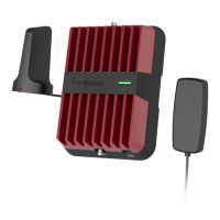
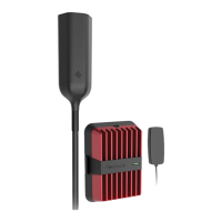
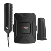
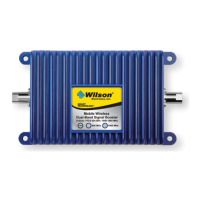
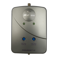
The weBoost Drive Reach Fleet is a professional vehicle cell phone signal booster kit designed to enhance cellular signal strength within a vehicle, supporting all networks, including 5G. This device aims to improve call quality, reduce dropped calls, and provide faster data speeds for users on the go.

Function Description:

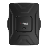
The Drive Reach Fleet operates by capturing existing weak cellular signals outside the vehicle, amplifying them, and then rebroadcasting the stronger signal inside the vehicle. This process works in reverse as well, taking the amplified signal from your cellular device and sending it back to the cell tower. The kit includes an outside NMO antenna, an in-vehicle antenna, a Drive Reach booster, and a power supply. The NMO (New Motorola) outside antenna is designed for permanent installation on the vehicle's roof, ensuring optimal signal capture. The in-vehicle antenna is placed inside the cabin to distribute the boosted signal to cellular devices. The booster unit itself is the core component, responsible for amplifying the signals. The system is designed to be compatible with various vehicle types, offering both a CLA (cigarette lighter adapter) and a hardwire power option for flexible installation. The hardwire option allows for a more integrated and permanent power connection, ensuring the booster only draws power when the vehicle's ignition is on, thus preventing battery drain.

Usage Features:

The primary usage feature of the Drive Reach Fleet is its ability to provide a stronger, more reliable cellular signal for multiple users within a vehicle. This is particularly beneficial for fleet vehicles, commercial trucks, or any professional setting where consistent communication is crucial. The booster supports all major cellular bands, including 5G, ensuring broad compatibility with current and future cellular technologies.

Installation is guided by a comprehensive manual, which also recommends using the weBoost App for an interactive setup experience. The app can walk users through the entire installation process, from identifying the best location for the outside antenna to connecting all components.

Key steps for installation include:

  1. Drilling a Cable Entry Hole: This involves identifying an optimal location on the vehicle's roof for the NMO outside antenna. The recommended spot is near the center of the roof, at least 12 inches away from other antennas and windows. A "soft install" is suggested first, where cables are routed temporarily to verify system functionality before drilling. Once the location is confirmed, protective tape is applied, and a 3/4" hole is drilled.
  2. Mounting the NMO Outside Antenna: After drilling, the NMO mounting cable is inserted through the hole. Silicone grease is applied to the o-ring on the collar to ensure a watertight seal when the collar is screwed onto the base mount. For a professional look and protection, the cable is routed under the headliner and down through the side trim panel to the booster's location. Before attaching the antenna itself, a thin layer of silicone grease is applied to the antenna o-ring and the threads of the NMO mount, then hand-tightened. It's crucial not to apply grease to the antenna pin contact surface.
  3. Mounting the In-Vehicle Antenna: The in-vehicle antenna can be mounted on the side of a seat or on the dash. It should be positioned at least 18 inches but no more than 36 inches from where the cellular device will be used. Velcro® or a 2-sided adhesive strip is provided for attachment.
  4. Hardwiring to Power: The kit offers both CLA and hardwire power options. For hardwiring, the vehicle's fuse box is located (referencing the owner's manual). The power cable is routed from the booster to an ignition-switched fuse slot. This ensures the booster powers off with the vehicle, preventing battery drain. A fuse tap (not included) is used to connect the positive lead, and the negative lead is connected to a factory grounding point.
  5. Connecting Coax Cables to Booster: The cable from the NMO outside antenna is connected to the "Outside Antenna" port on the booster. The cable from the in-vehicle antenna is connected to the "Inside Antenna" port.
  6. Connecting Power Supply to Booster: Finally, the power supply cord is connected to the "12V DC" port on the booster. It's important to connect both antennas before connecting the power supply.

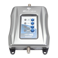
Once powered on, the booster's light patterns provide feedback on its operational status. A solid green light indicates proper functioning. A blinking red, then solid green light, suggests a reduction in power due to oscillation (feedback loop), but if desired signal boost is achieved, no further adjustments are needed. A solid red light indicates a complete shutdown of a band due to oscillation, requiring troubleshooting. If the light is off, the power supply should be checked.

Maintenance Features:

The Drive Reach Fleet is designed for minimal maintenance once installed correctly.

  • Troubleshooting Light Patterns: The booster's LED indicator provides immediate feedback on its status. If a blinking red or solid red light appears, indicating oscillation, the primary troubleshooting step involves increasing the separation distance between the inside and outside antennas. This helps prevent signal feedback that can cause the booster to reduce power or shut down.
  • Power Cycle Reset: If issues persist, the booster can be reset by disconnecting and reconnecting its power supply. This initiates a new power cycle, which can resolve temporary glitches.
  • Customer Support: weBoost provides customer support via phone and their website for any difficulties encountered during installation or operation.
  • Warranty: The device comes with a 2-year warranty against defects in workmanship and materials, offering peace of mind for users. Replacement products may include refurbished units that meet product specifications.

The device is a CONSUMER device and requires registration with the wireless provider. It must be operated with approved antennas and cables, and antennas must be installed at least 8 inches from any person. The system is designed to amplify signals without altering them, and it includes safety features to prevent harmful interference with cell towers, such as automatic gain reduction and band shutdown in case of oscillation.

Wilson Electronics weboost DRIVE REACH FLEET Specifications

General IconGeneral
CategoryExtender
Max Gain50 dB
Gain50 dB
Power Output20 dBm
Power Supply12V DC
Impedance50 Ohm
Weight2.5 lbs
Product TypeSignal Booster
Technology4G LTE
Frequency Bands700 MHz, 850 MHz, 1900 MHz
Power12V

Related product manuals