3
ConnecT 2.0 Runs with Togo Installation
Choosing a Location for the Antenna & Power Supply
Before mounting the antenna, determine a location for the wall plate/power
supply. Keep in mind the following:
• A coaxial cable will have to run from the power supply to the antenna and from
the power supply to each television (up to 4 TVs if using the WP2-600).
• A connection must be made from the ConnecT 2.0 to the back of the power
supply and from the power supply to a RV power source.
Choose a location for the antenna that meets the following requirements:
• Offers enough support for a secure installation
• Maintains adequate clearance from the edge of the roof and any obstructions
– clearance distance of 24" needed from the antenna to front of the vehicle
– clearance distance of at least 12" needed from the antenna to nearest
obstruction and to the edge of the roof
Option A ConnecT 2.0 with WP2-600 Wall Plate
EXTERIOR
Step 1 – Select a level spot on your roof for installation. Level the base front-to-
back and side-to-side.
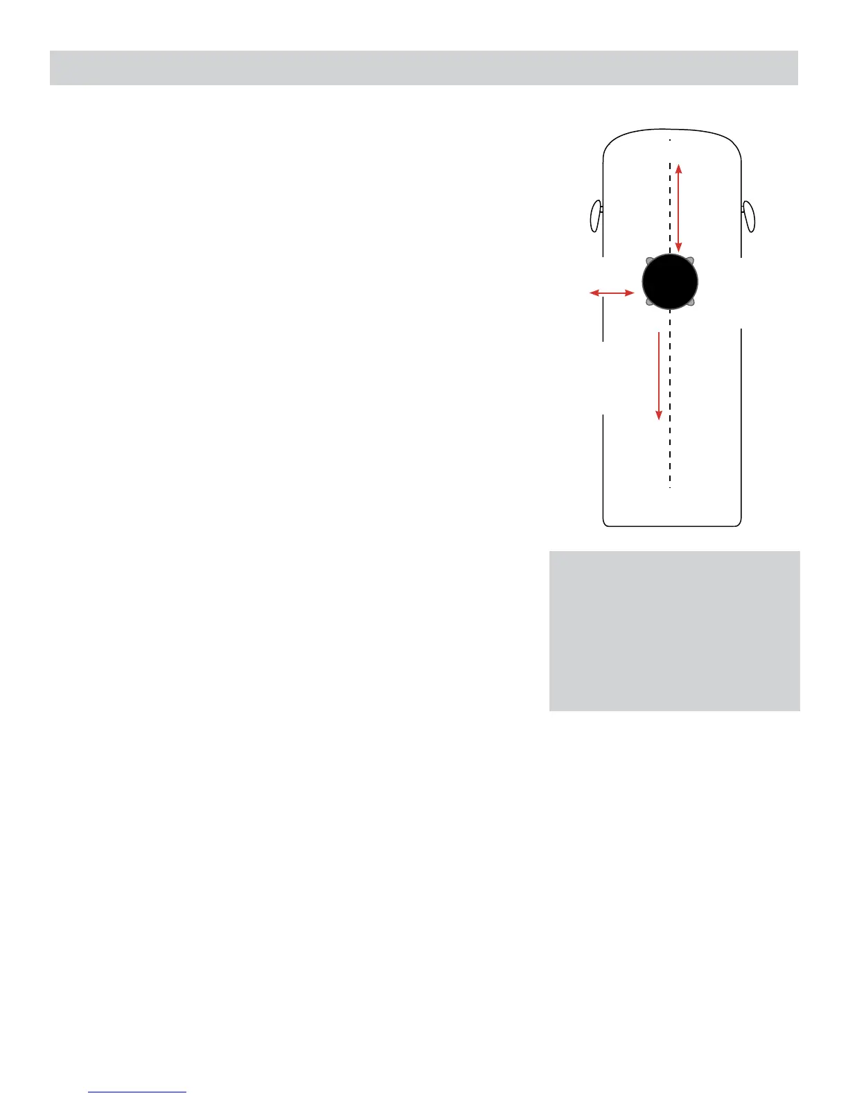
Step 2 – After selecting a location for the antenna, make sure that the center
line of the antenna is on or parallel to the center line of the vehicle; the center
line of the antenna runs through the point between the two feet where cable
connections are located.
Step 3 – Position the antenna with cables exiting toward the rear of the vehicle.
To ensure proper installation, verify that the distance from the edge of the roof to
any foot is at least twelve inches.
Step 4 – Place the unit on the roof in its permanent location, and mark around
each base foot.
Step 5 – Apply sealant in the areas marked for the base feet. Place the base feet
on top of the sealant. Screw down each foot and put sealant around the edge of
feet and over each screw (use only manufacturer approved screws and sealant).
Step 6 – Decide the best location for the power cable and coax cable to enter the
vehicle, as well as the location of the wall plate power switch inside your vehicle.
Drill a ¾” hole in the roof, and push the power cable and coax cable inside,
making sure the cable is accessible from the area where the power supply will
be located.
Step 7 – Place the provided cable entry plate over the hole and cables. Screw
the plate in place. Seal the plate and screw holes with sealant.
INTERIOR (see diagram on page 4)
Step 8 – For a wall or panel mount, drill or use a hole saw to create a 1¼” hole.
Pull the wires through the wall or panel.
Step 9 – After connecting to the ConnecT’s power cable, run the red wire to the
spade terminal labeled WiFi+, located in the middle of the electronics board on
the backside of the wall plate. Next, run the black wire to the spade terminal
labeled WiFi-, also located in the middle of the electronics board.
Step 10 – Run a dedicated power cable to the fuse panel or RV power source
with an inline 3 amp fuse. Run a ground cable to the vehicles chassis.
Step 11 – Connect the coax cable coming from the antenna to the ANT IN input.
Step 12 – There is an option to run a coax cable to an outside receptacle for park
cable. If doing so, connect that cable to the PARK CABLE IN input.
12V DC Wiring Requirements
• Supply voltage – 9-16V
• Max operating current – 1A
• Max operating temperature – 60C
• Max power cable length – 50 ft
(18 gauge wire recommended)
• 3A Fuse
3
Front of Vehicle
Cable
connections
must face back
of vehicle
At least
12”
Mount on
or parallel to
center line of
coach
Back of Vehicle
At least
24”
 Loading...