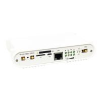
Step 14 – Before connecting the power cable to the Gateway confirm that all
connections are properly made. If so, connect the power cable. Turn the wall
plate power switch to the ON position and verify that the LED on the backside
of the Gateway illuminates.
Step 15 – There will be two mating
hooks on the side opposite the
cabling hole and one on the same
side as the cabling hole. Once the
Gateway is secured to the hooks
(1), slide the Gateway towards the
lever until it locks into place (2).
A clicking sound indicates the
Gateway is locked in position.
Step 16 – Carefully reinstall the dome with the four screws previously removed.
Installation (cont.)
1
2
7" MAX ROOF THICKNESS
OPTION 4 - GATEWAY IN DOME
COMPATIBLE WITH ROOF RADIUS OF 230 INCHES TO FLAT
GATEWAY
1" HOLE IN ROOF
ETHERNET CABLE (OPTIONAL)
ANT IN
TV OUT 1
TV OUT 2
TO ANT IN
RED WIRE - TO SWITCH
BLACK WIRE - TO GROUND
+12V DC
GROUND
+12V DC
3A FUSE RECOMMENDED
OTA CABLE
WIFI POWER CABLE
Compatible with roof radius
of 230 inches to flat
Gateway
1" hole in roof
OTA cable
WiFi power cable
+12V DC
Red wire to switch
Black wire to ground
Ethernet cable (optional)
TV out 2
TV out 1
+12V DC
Ant in
Ground
7" max roof thickness
To Ant in
3A fuse recommended
8
2
1
B. Air 360
+
In Dome Install Diagram
 Loading...