Maintenance
3303−2/A1
RT-flex58T-E
Winterthur Gas & Diesel Ltd.
3/ 4
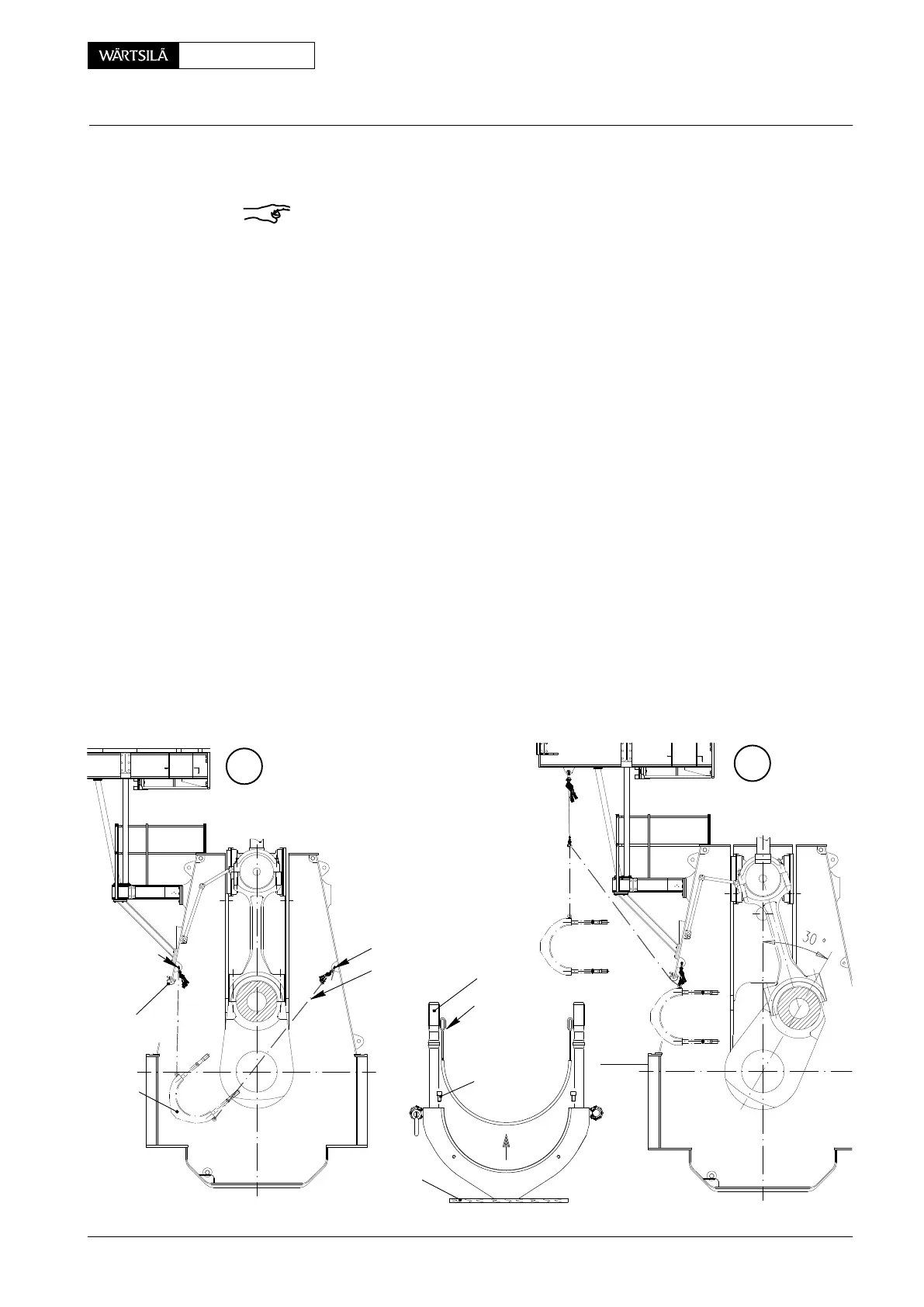
1.4 Removal of bearing cover
Remark: Only with a lifting tool having at least 3.5 m hoisting capacity, instead of
manual ratchet ’H1’, the bearing cover can be removed directly from the crankcase
bottom (Fig. ’A’).
⇒ Fit a RUD-eye bolt ’RC’ on each side of bearing cover 4.
⇒ Mount deviation pipe GF 94117A to the column door.
⇒ Attach manual ratchet ’H1’ with shackle 94572C. Attach manual ratchet ’H2’
with shackle 94572C and rope 94120B.
⇒ Remove nuts 2.
⇒ Carefully lower the bearing cover until the connecting rod studs 1 are out of
the connecting rod.
⇒ Turn crankshaft about 30° in exhaust side direction.
⇒ Slacken manual ratchet ’H2’ until the bearing cover is moved in position as
shown in Fig. ’C’
⇒ Lift bearing cover with manual ratchet ’H1’ as high as possible. Disconnect
manual ratchet ’H2’
⇒ Attach manual ratchet ’H3’ with rope 94120G, move bearing cover out of
column and place it on wooden underlay ’WU’.
1.5 Removal of lower bearing shell
⇒ Remove Allen screws 9.
⇒ Remove bearing shell by means of handle screws 94009-M8 which are
screwed into the front faces of the bearing shell.
D
C
H2
GF 94117A
H1
94120G
H3
94009−M8
9
WU
94120B
WCH01025
H1
4
1
94572C
94572C
V2 / 2013
Inspection, Removal and Fitting of Bottom End Bearing