Maintenance
8733−1/A2
RT-flex58T-E
Winterthur Gas & Diesel Ltd.
1/ 3
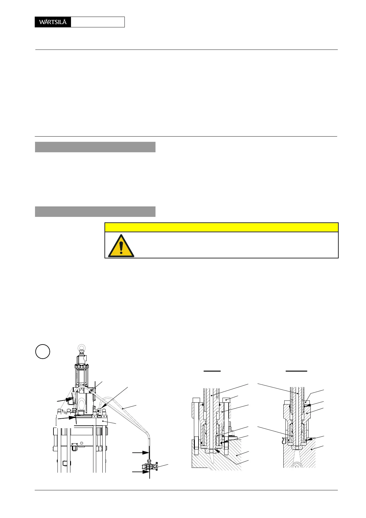
Tools: Key to Illustrations:
1 Regrinding device 94871 1 Cylinder cover 9 Screw
1 94871A 2 Injection valve 10 Pipe bracket
1 Special spanner 94874 3 Injection control unit 11−14 O-ring
1 Torque wrench 4 HP injection pipe 15 Flange
5 Claw
6 Thrust ring SF Sealing face
7 Flange EC Emery cloth
8 Screw HD Hand drill
1. Preparation
⇒ Stop the engine.
⇒ Do the the instruction in Operation Manual, 0510−1, to release the pressure in
the fuel rail.
⇒ Make sure that there is no pressure in the fuel rail.
⇒ Set to off the electrical trace heating and remove the insulation from HP injec-
tion pipe.
2. Removal
CAUTION
Damage Hazard: Make sure that you do not damage the sealing
faces or the HP injection pipes.
⇒ On the applicable HP injection pipe 4, disconnect the electrical connection on
the injection valve 2.
⇒ Remove the applicable pipe brackets 10.
⇒ On the injection valve 2, remove the four screws 8 from the flange 7.
⇒ On the flange 15, remove the four screws 9.
⇒ Carefully remove the applicable HP injection pipe 4 from the injection valve 2
and the injection control unit 3.
⇒ Apply protection to the sealing faces ’SF’ and the open ends of the HP injec-
tion pipe 4.
I
I - I
A
II -II
I
2
4
10
2
8
7
15
9
3
3
4
II
II
1
12
5
SF
WCH02566
13
14
2014−07
HP Fuel Pipe to Injection Valve (for ICU Mk3)
Removal, Grinding and Installation