Maintenance
8733−1/A2
RT-flex58T-E
Winterthur Gas & Diesel Ltd.
3/ 3
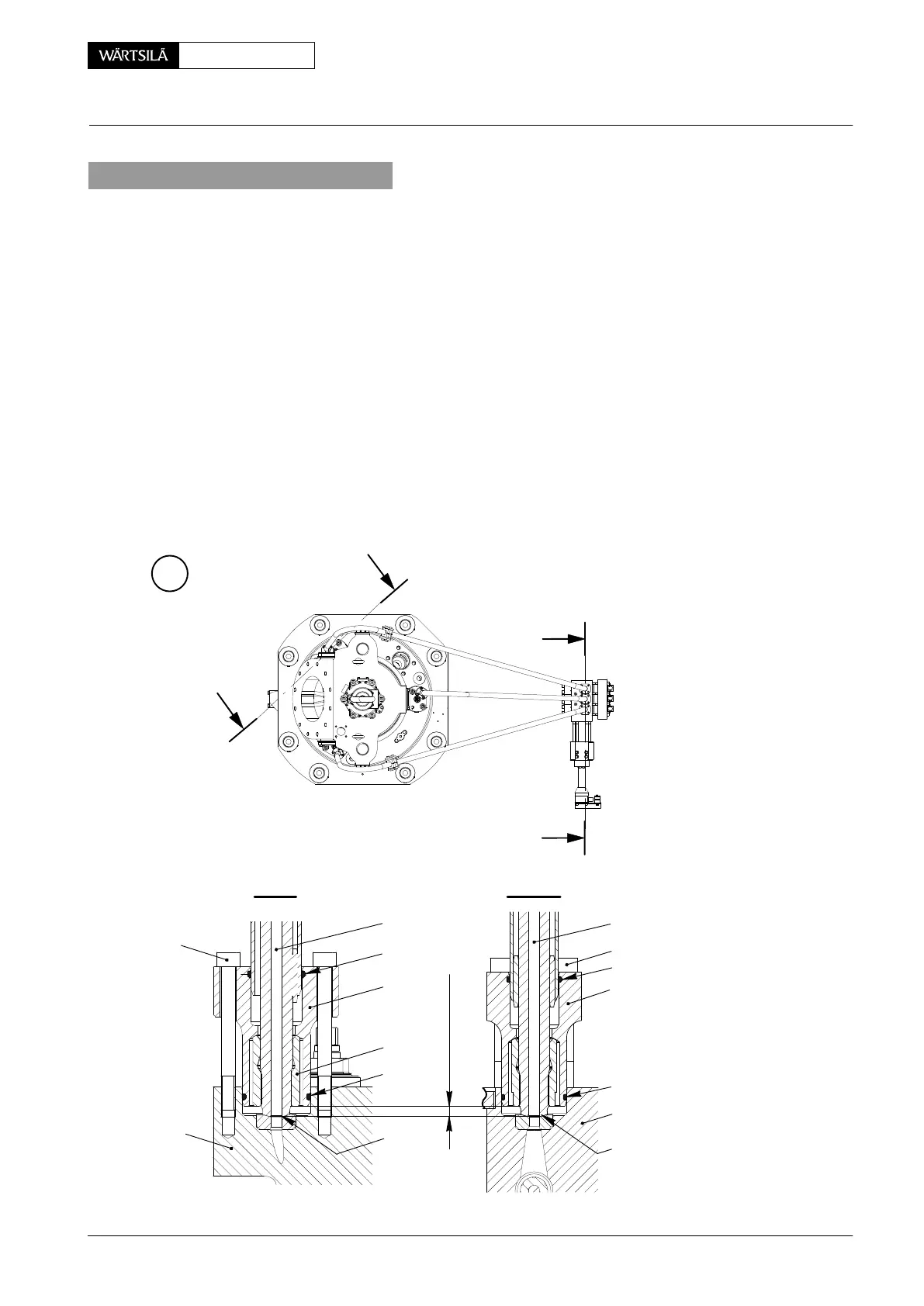
4. Installation
⇒ Use the special spanner 94874 to install the pipe claw 5.
⇒ Make sure that the claws 5 are correctly attached to HP injection pipe, i.e. that
the claw 5 are adjusted to the end of the thread on the pipe.
⇒ Make sure that there is a distance of X = 6 1 mm between the claw 5 and the
HP injection pipe 4.
⇒ If necessary, use an open-ended wrench to adjust the claw 5.
⇒ Remove all of the protection from the sealing faces ’SF’ in the injection valve 2
and the injection control unit 3.
⇒ Apply Never-Seez NSBT-8 to threads of screws 8 and 9.
⇒ Carefully put the HP injection pipe 4 in position in the injection valve 2 and the
injection control unit 3.
⇒ Torque symmetrically the four screws 8 to 25 Nm.
⇒ Torque symmetrically the four screws 9 to 25 Nm.
⇒ Install the applicable pipe bracket 10.
E
I
WCH02566
WCH02566
I
II
II
I - I
II -II
2
8
7
15
9
3
4
12
5
11
X = 6 1 mm
SF
SF
13
14
4
2014−07
HP Pipe to Injection Valve: Removal, Grinding and Installation