Maintenance9223−1/A1
RT-flex58T-E
Winterthur Gas & Diesel Ltd.
12/ 22
008.744/01
008.744/01
008.743/01
008.742/01
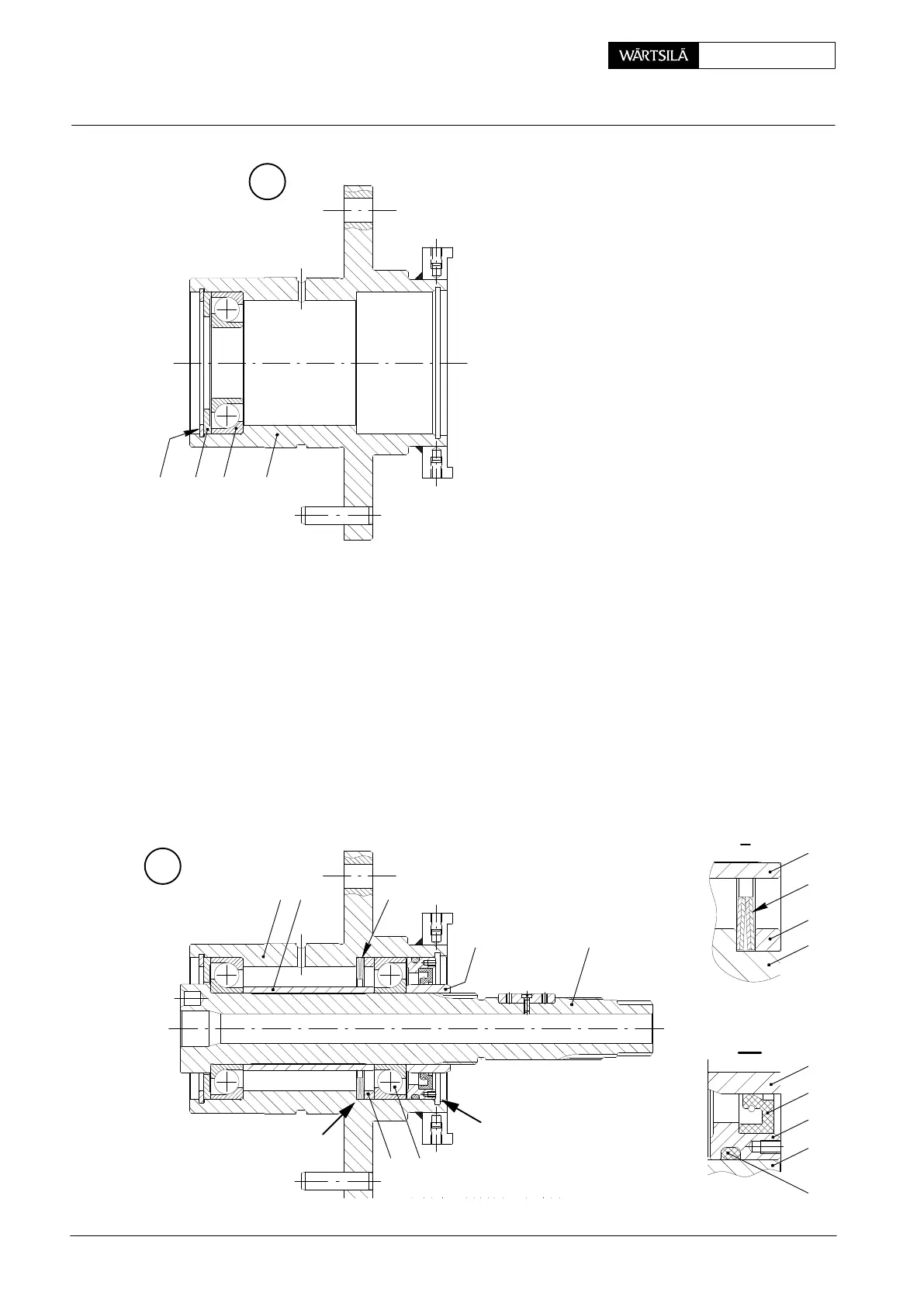
6.2 Sub-assembly of bearing housing
⇒ Remove the parts which are fitted on shaft 5
as shown in Fig. ’O’.
⇒ Oil ball bearing 32a and insert it into housing
14. Pay attention to the fitting position in para-
graph 6.1!
⇒ Place disc 37 with its smaller seating surface
pointing to the ball bearing and fit circlip 36.
6.3 Completing of the bearing housing
⇒ Oil all parts.
⇒ Fit shaft 5.
⇒ Push distance sleeve 34 onto the shaft.
⇒ Fit disc springs 35 according to view I.
⇒ Fit distance ring 33 with thickness ’x’ determined under paragraph 6.1.
⇒ Oil ball bearing 32 and insert it into housing 14. Pay attention to the fitting
position in paragraph 6.1!
⇒ Fit retaining ring 29 with new sealing ring 30 and O-ring 60 according to view
II.
⇒ Fit distance ring 31.
31
30
29
14
33
14
35
II
I
34
Q
1432a3736
R
33
3514
34
31 5
32
I
II
2013
Crank Angle Sensor Unit: Dismantling, Assembling and Adjusting